McIntosh is one of the most dependable brand names when it comes to high-end audio systems. For years the brand has been recognized by audiophiles throughout the world as equipment that delivers clear and consistent quality in music. McIntosh is probably best known for its amplifiers and preamps, but the company produces many other components and parts for stereo and home theatre.
What are the specs for the McIntosh MC 2250?
- Power Output:
- 250 watts per channel into 8Ω (stereo), 500 watts into 8Ω (mono)
- Frequency Response:
- 20Hz to 20kHz
- THD:
- 0.02%
- Damping Factor:
- 30
- Input Sensitivity:
- 0.75V
- Signal to Noise Ratio:
- 95dB
- Speaker Load Impedance:
- 1Ω to 8Ω
- Semiconductors:
- 9 x IC, 76 x transistors, 37 x diodes
- Dimensions:
- 177 x 406 x 368mm
- Weight:
- 36.3kg
- Year:
- 1982
What else to know about the McIntosh MC 2250?
**INPUT AMPLIFIER** Each channel contains a complete seven transistor low power input amplifier. An input differential transistor pair provides high input impedance and low noise. The outputs of this pair are combined in a current mirror circuit which drives a class A amplifier stage. The output stage follows this amplifier and is a complementary pair of transistors biased class AB. The output signal drives the metering circuit, headphone jack, and the high power output amplifier. This discrete transistor amplifier design was selected for low noise, low distortion, adequate power output capability to drive headphones, and freedom from turn on and turn off transients. In the MONO mode of operation the input signal feeds only the right input amplifier via the RIGHT/ MONO GAIN control. The right input amplifier feeds both output power amplifier sections. When MONO BRIDGE MODE is selected the left channel input amplifier is used as a phase inverter. The output channels then operate 180° out of phase with respect to each other which is the correct arrangement for bridge output connections. When the MONO PARALLEL MODE is selected the channels operate in phase. The channels, of course, also operate in phase for the STEREO MODE. **OUTPUT POWER AMPLIFIER** The input amplifiers feed the output amplifiers through an electronic switch. The switch eliminates turn-on and turn-off transients and is used for speaker switching. A junction FET and LED/light dependent resistor network make up the switch. This combination allows the lowest possible distortion when the amplifier is on and the highest isolation when the amplifier is off. The control signal to the switch is off during the auto test countdown. Therefore, transients that may come into the amplifier from source equipment will not be amplified or reach the loudspeaker. Since the HEADPHONE output and meters are powered by the input amplifier, their operation is not affected by the SPEAKER switch or the turn on delay system. The first stage of the output power amplifier is a differential transistor pair biased for best linearity. The offset to the differential pair is adjustable. Correct adjustment allows the lowest possible distortion at low frequencies. A current mirror circuit combines the differential outputs into one signal which is then amplified by a following class A voltage amplifier. Both the differential transitors and the voltage amplifier are supplied by active current sources. The results are lower distortion and cleaner turn-on characteristics. The driver stage follows the voltage amplifier. The driver consists of a complementary pair of power transitors biased class AB. Next, three complementary pairs of rugged power transistors make up the power output stage. All power transistors are mounted on conservatively sized anodized aluminum heat sinks. Because of a unique connection of the bias network, the output transistors operate class B and exhibit no crossover distortion often associated with class B operation. The heat sinks, therefore, remain cool when there is no output. The amplifier output signal is fed to the output terminals through the output autotransformer. The Mclntosh designed interleaved multifilar wound autotransformer is used to properly match the amplifier to stereo output load taps for 1, 2, 4 and 8 ohms. The MC 2250 will deliver full power over the entire audio frequency range at any of these impedances. The autotransformer also protects speakers from damage in the event of amplifier failure. Should a direct current component appear in the output, it is shunted through the low DC resistance of the autotransformer. DC cannot damage the speaker. A Mclntosh patented Sentry Monitoring circuit constantly monitors the output signal and instantly reacts to prevent overload of the output transistors. At signal levels up to rated output this circuit has high impedance and has no effect upon the output. If the power output exceeds design maximum, the Sentry Monitoring circuit operates to limit the signal to the output transistors. In the event of a short circuit across the amplifier output or severe impedance mismatch the Sentry Monitoring circuit will protect the output transistors from failure. Both positive and negative halves of the output signal are monitored and protected independently. **POWER GUARD PROTECTION CIRCUIT** The Mclntosh patented Power Guard circuit eliminates amplifier clipping due to overdrive. The circuit also illuminates red LIMIT indicator lamps when the amplifier is driven beyond its maximum output capacity. Power Guard prevents loudspeaker damage and eliminates harsh output distortion caused by amplifier clipping. The Power Guard circuit consists of a waveform comparator which monitors the wave shape of the amplifier input and output signals. Normally there is no difference in wave shape between these signals and the comparator produces no output. When the amplifier is driven beyond its maximum power capacity a difference will develope. If this exceeds 0.5% (equivalent to 0.5% total harmonic distortion) the comparator output causes the red LIMIT indicators to light. If there is a further increase the comparator output activates an electronic attenuator at the amplifier input to reduce the amplifier gain, this automatic attenuator will hold the amplifier output to its maximum undistorted value regardless of the degree of overdrive to the amplifier. The amplifier may be overdriven by 20 dB before the output distortion exceeds 2%. The comparator is an especially compensated operational amplifier integrated circuit. Its output is detected by a full wave bridge that feeds signals to the control circuitry for the LIMIT and NORMAL indicators and to the electronic attenuator at the amplifier input. The attenuator is a light emitting diode/light dependent resistor network selected especially for its low distortion and proper time constant characteristics. **SYSTEM TEST CIRCUIT** When AC line power is applied to the MC 2250 the System Test circuit functions to verify operating potentials at 7 test locations within the amplifier. Upon applying power a digital display lights with the number 7. The digit is driven by a counter that steps down at a 1 second or .4 second rate. Each time the digit changes, electronic switches select the outputs of various voltage comparators connected to test points in the amplifier. If voltages are normal the green Power Guard lights flash, there is an audible beep produced by an internal sounder, and the display decreases to the next test number. When the count passes number 1 the loudspeakers connect and the display blanks off. If a fault condition exists the counter stops and both red Power Guard limit lights go on. The digit displayed indicates the circuit at fault. Servicing the amplifier is thereby simplified. The test circuit uses logic counter, BCD decoder, lamp driver, and voltage comparator integrated circuits. **POWER SUPPLY** The power supply is a conventional full wave bridge rectifier arrangement providing plus and minus 50 volts DC. Electronic regulators step down and regulate plus and minus 15 volt sources for low level circuits and plus 5 volts for the logic circuits. Thermistors are used in the power transformer primary circuit to limit the turn-on current.Brief History of McIntosh
Long mapped-to Binghamton New York – the current headquarters and manufacturing center for McIntosh Labs – not many people know the brand was originally launched outside of the Nation’s Capital in Silver Spring Maryland, in 1949. In 1956, the brand built their original facility in New York, according to the official brand website.
Other McIntosh Products We Often Buy
Typically, StereoBuyers purchases mostly used amplifiers, especially the vintage amps and high-end McIntosh models such as the MC202 or MC252, and the C220 preamp, for example. We have also purchased many pre-owned tuners from McIntosh over the recent years, including the MR67 and MR78 models, for example.
StereoBuyers has purchased tens of thousands worth McIntosh brand equipment since 2014, with individual buys ranging from $100 to well over $50,000. If you are moving, ready to upgrade, or have McIntosh equipment you do not or will not be using, why not contact us today to find out if it is worth good money?
If you are interested in selling your used McIntosh equipment to us in the greater NYC area or Colorado, please click here to fill out a Free Quote Form and we will get back to you. If we agree on terms, we come to meet you where you want, and pay cash.
The following images show actual McIntosh equipment purchased by StereoBuyers.
-
McIntosh C 31V
Preamplifier - av control center -
McIntosh MA 7000
Integrated amplifier -
McIntosh MAC 1700
Receiver -
McIntosh MC 162
Power amplifier -
McIntosh MC 2102
Power amplifier -
McIntosh MC 2205
Power amplifier -
McIntosh MC 2250
Power amplifier -
McIntosh MC 2600
Power amplifier -
McIntosh MC 7150
Power amplifier -
McIntosh MCD 301
Sacd / cd player -
McIntosh MHP 1000
Headphones -
McIntosh C 35
Preamplifier -
McIntosh ML 1C
Speakers -
McIntosh MLD 7020
Laser disc player -
McIntosh MQ 101
Equalizer -
McIntosh MR 500
Tuner -
McIntosh MR 73
Tuner -
McIntosh MR 74
Tuner -
McIntosh MR 77
Tuner -
McIntosh MR 88
Tuner -
McIntosh MX 110
Tuner preamplifier -
McIntosh MX 112
Tuner preamplifier -
McIntosh C 39
Preamplifier -
McIntosh MX 130
Tuner preamplifier -
McIntosh MX 136
Audio / video preamplifier -
McIntosh C 8
Preamplifier -
McIntosh C 2500
Preamplifier -
McIntosh C 49
Preamplifier -
McIntosh CR 16
Preamplifier -
McIntosh MA 6400
Integrated amplifier -
McIntosh MAC 4100
Receiver -
McIntosh MC1.2KW
Power amplifier -
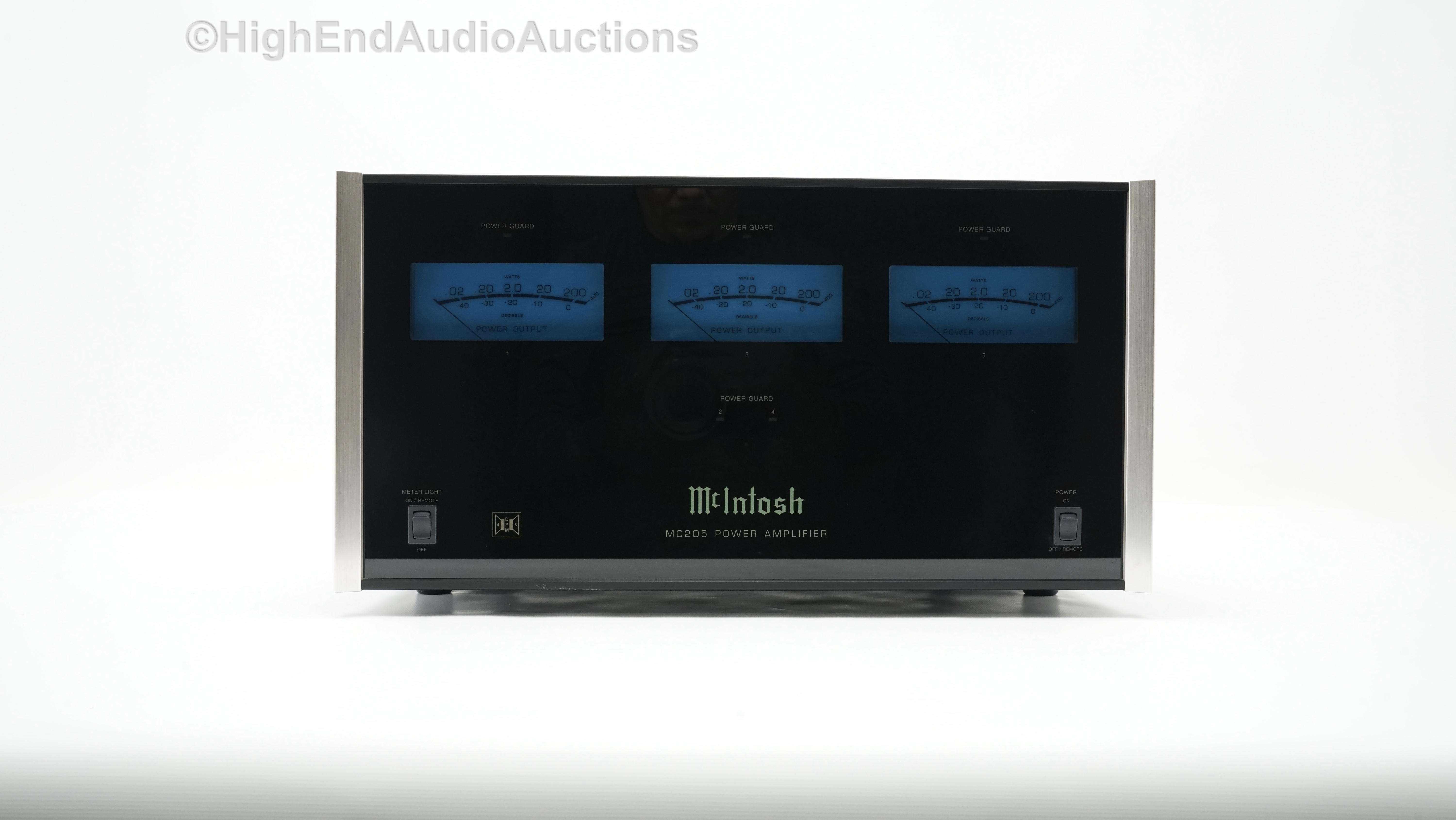
McIntosh MC 205
Power amplifier -
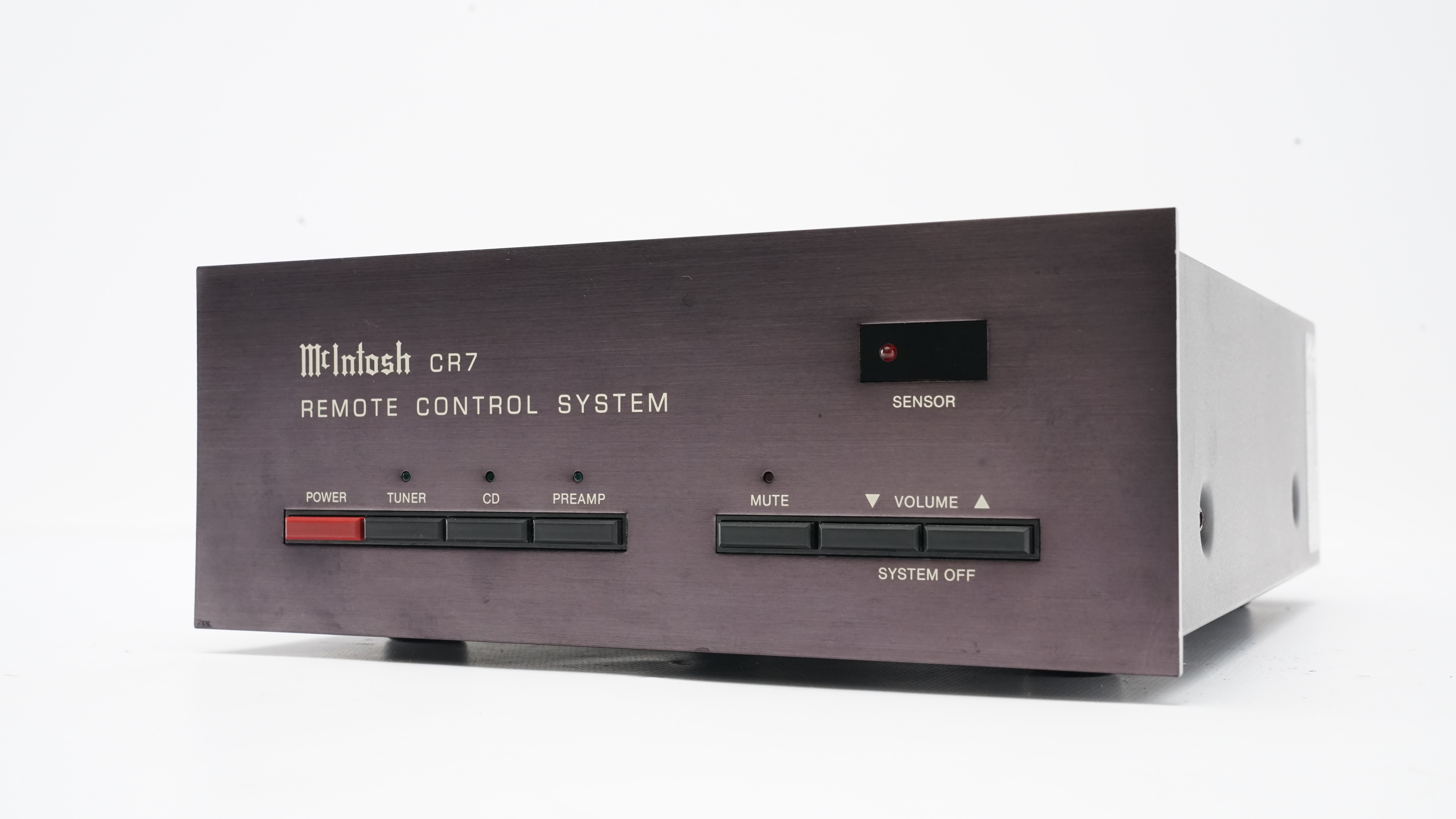
McIntosh CR 7
Remote control system / preamplifier -
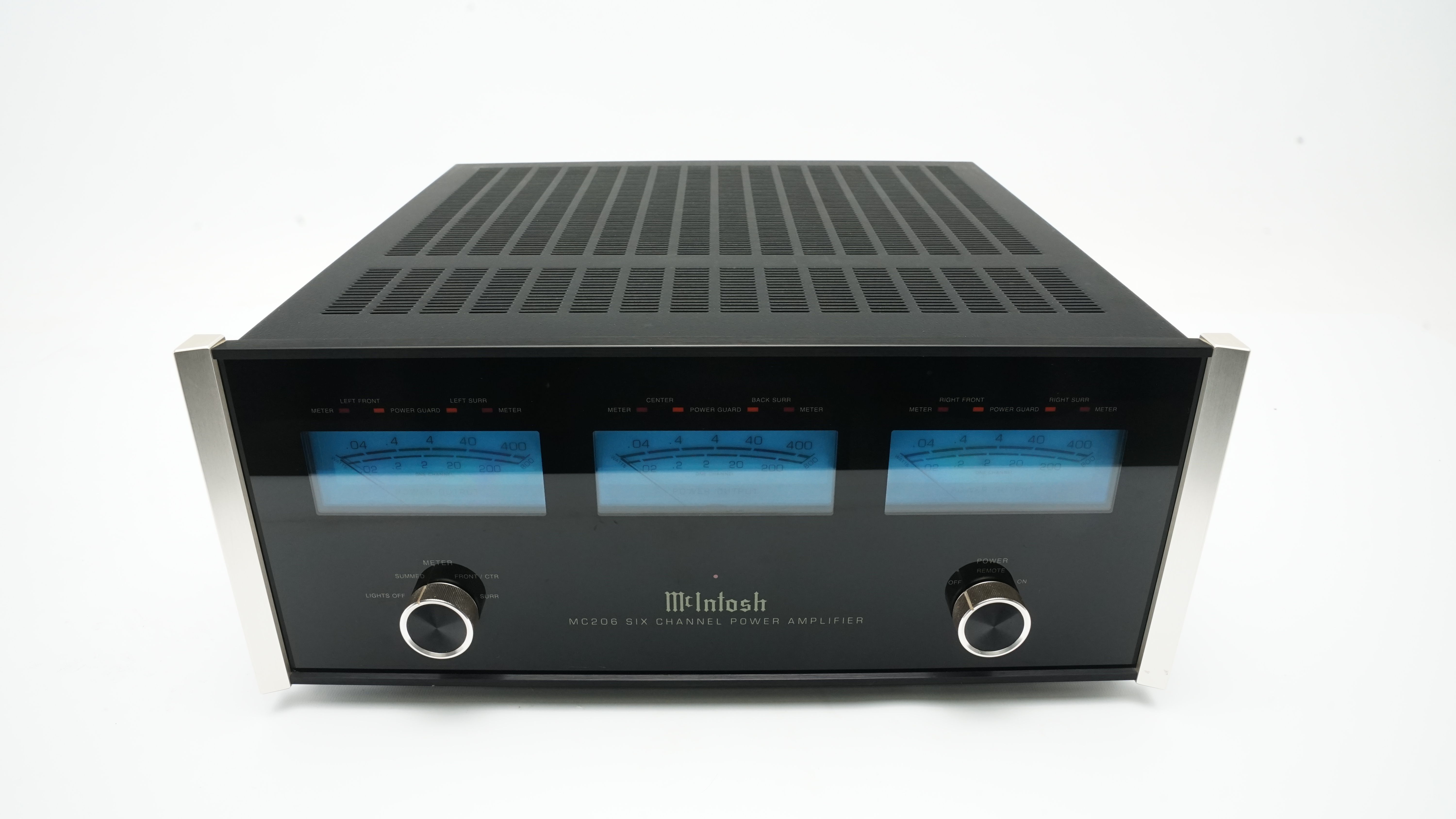
McIntosh MC 206
Power amplifier -
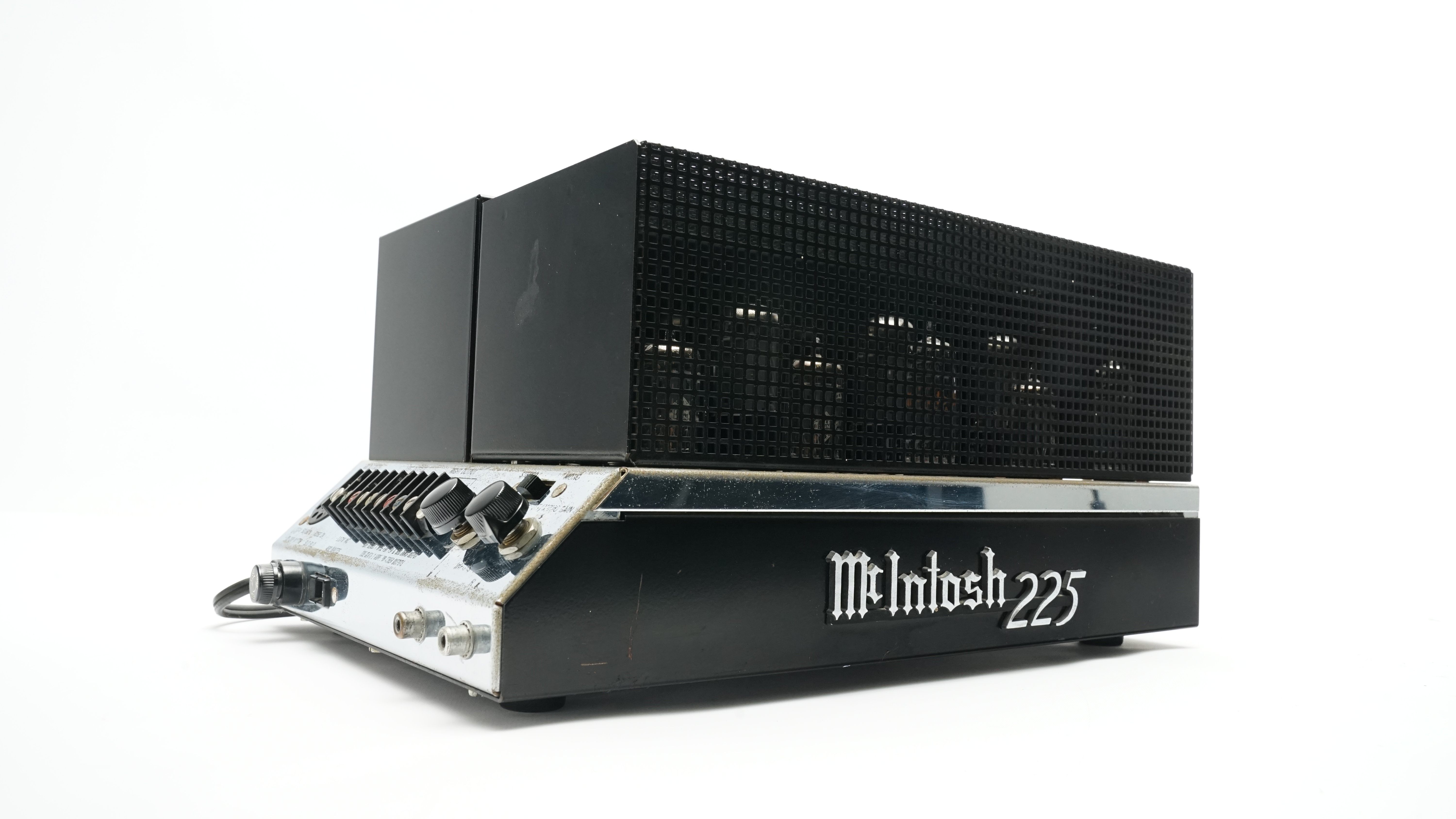
McIntosh MC 225
Power amplifier -
McIntosh MCD 205
Cd player -
McIntosh MPC 500
Power controller -
McIntosh MVP 861
Universal disc player -
McIntosh MX 120
Preamplifier -
McIntosh MX 122
Preamplifier -
McIntosh XLS 360
Speakers -
McIntosh CR 8
Remote area controller -
McIntosh MX 135
Preamplifier -
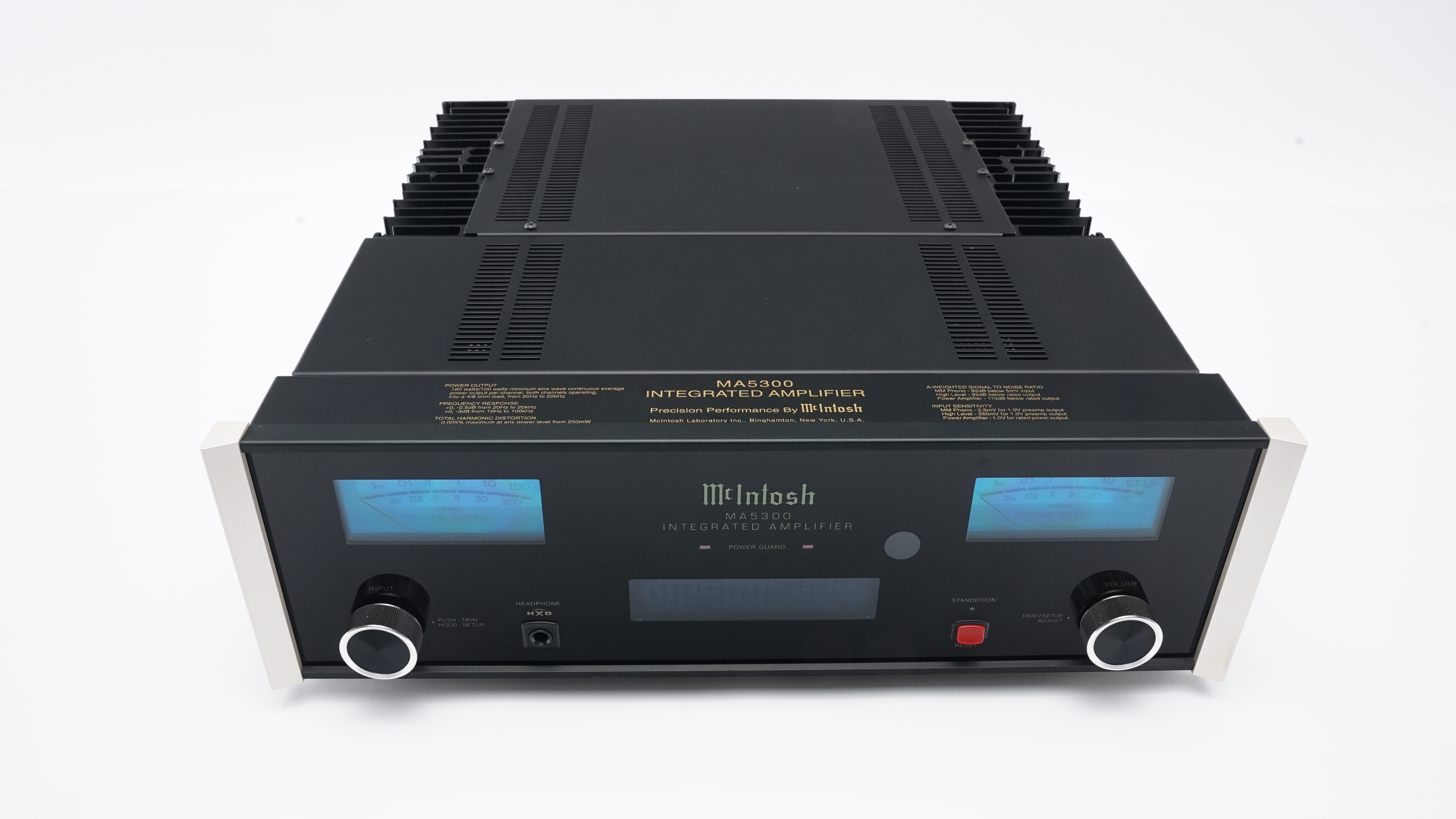
McIntosh MA 5300
Integrated amplifier -
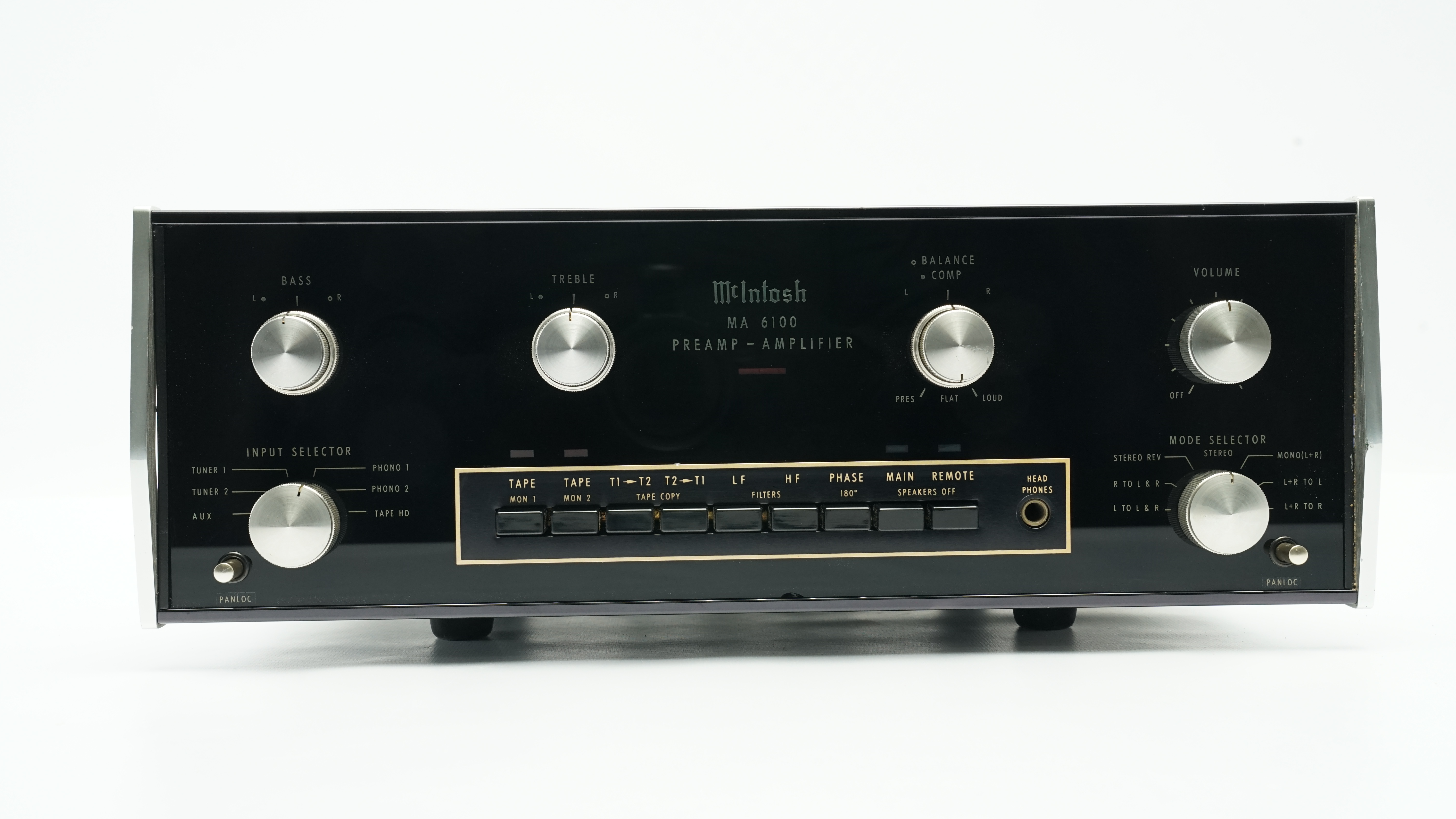
McIntosh MA 6100
Integrated amplifier -
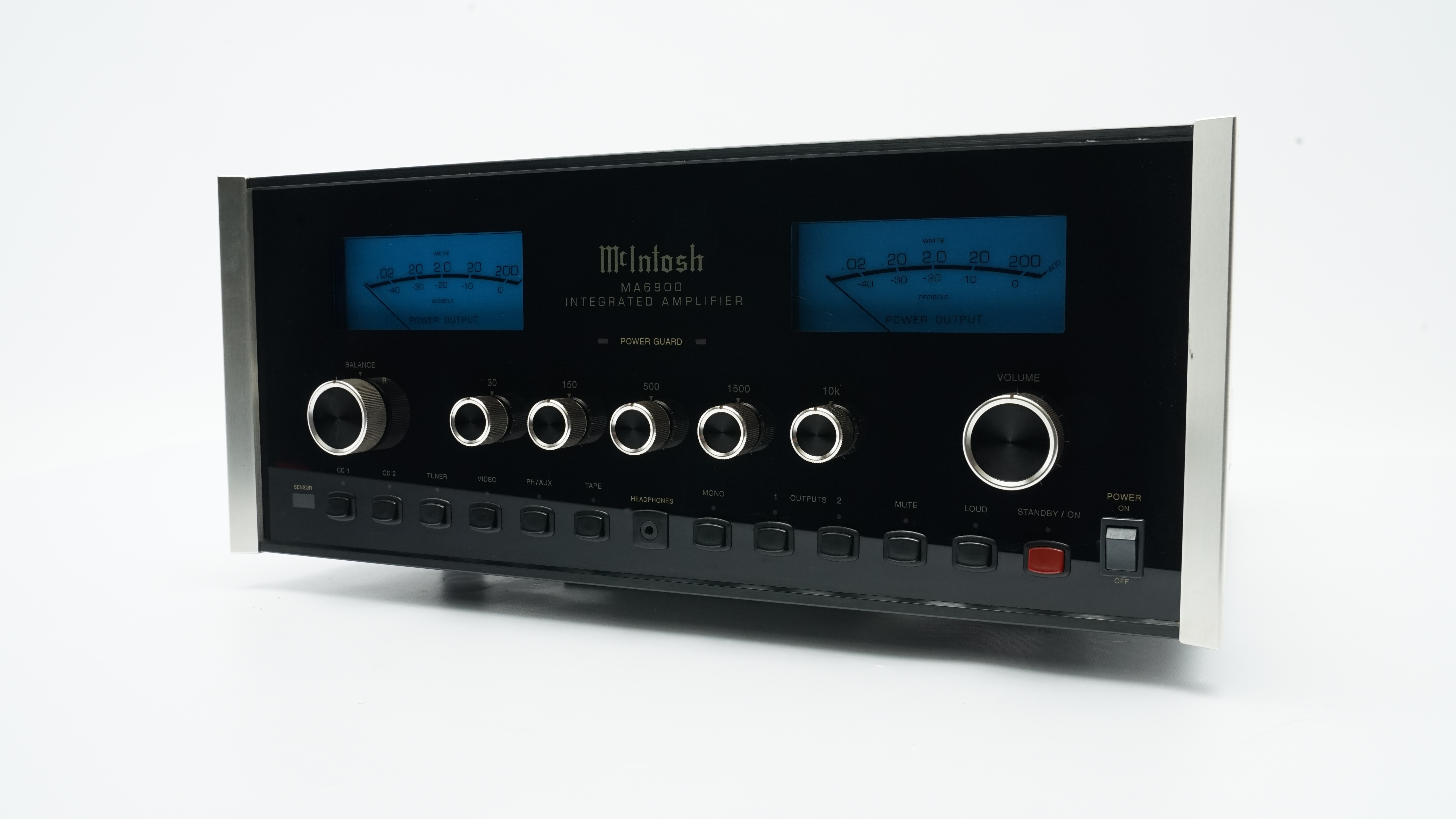
McIntosh MA 6900
Integrated amplifier -
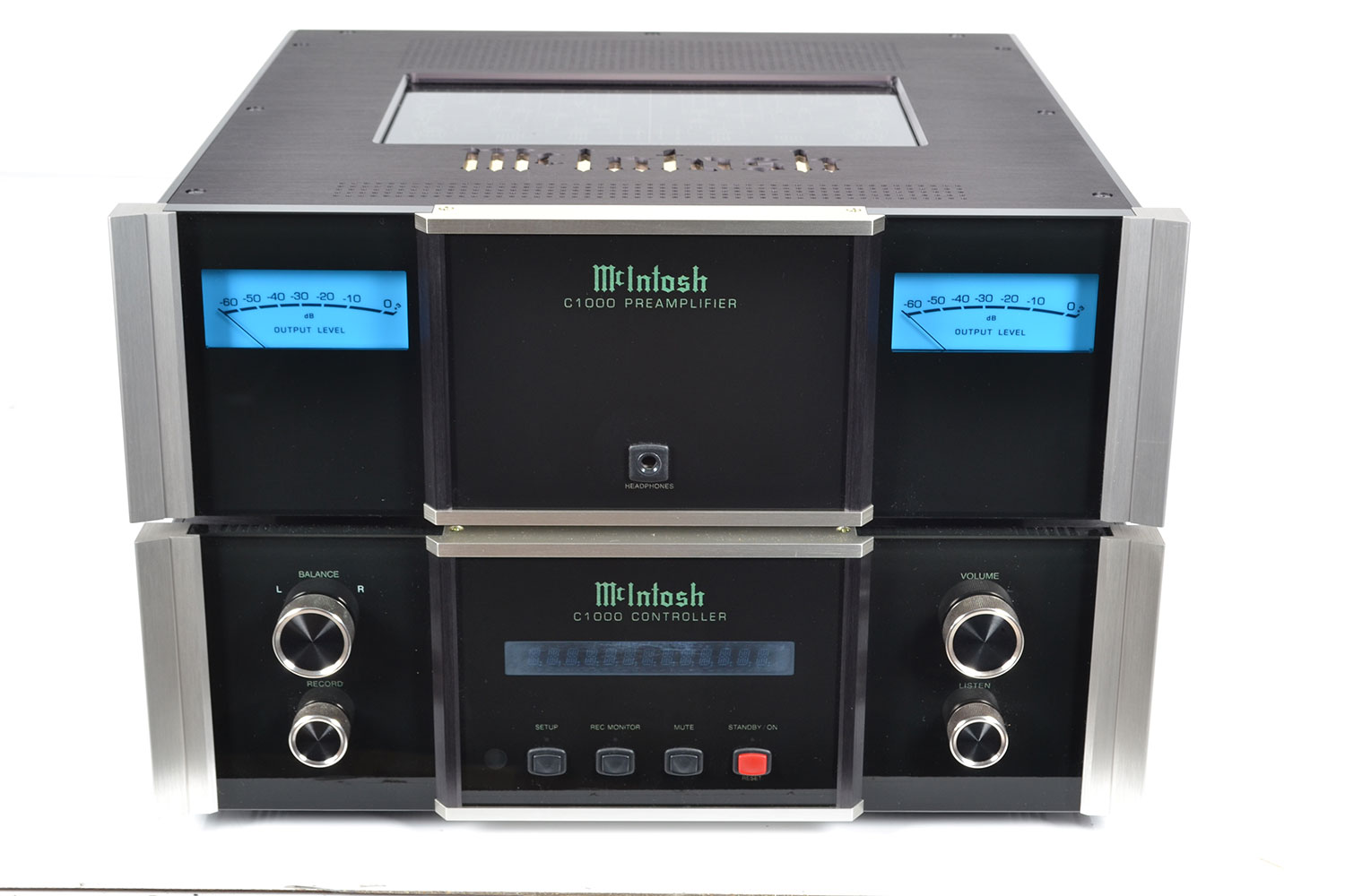
McIntosh C 1000p/1000C
Preamplifier -
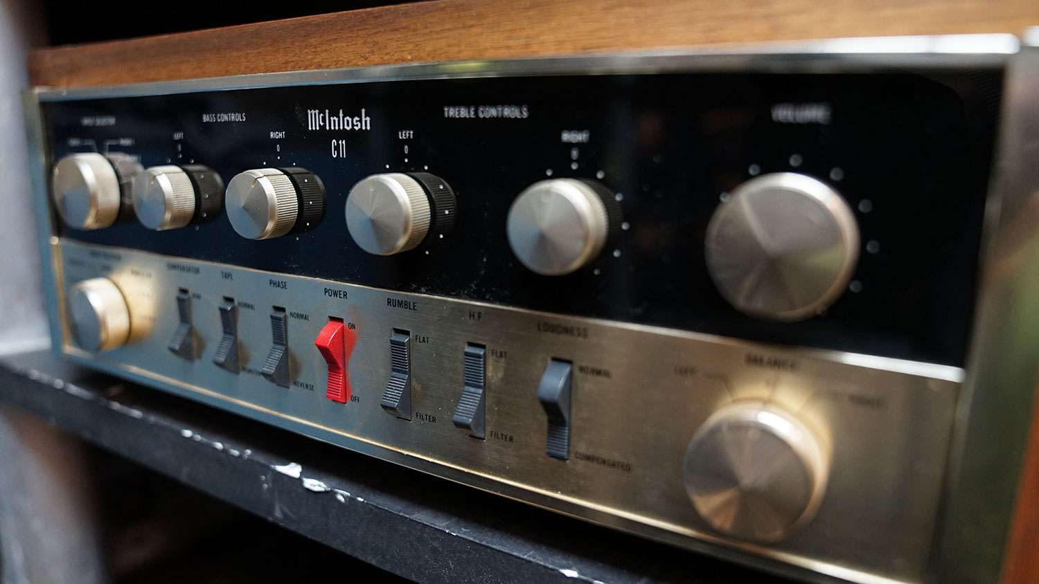
McIntosh C 11
Preamplifier -
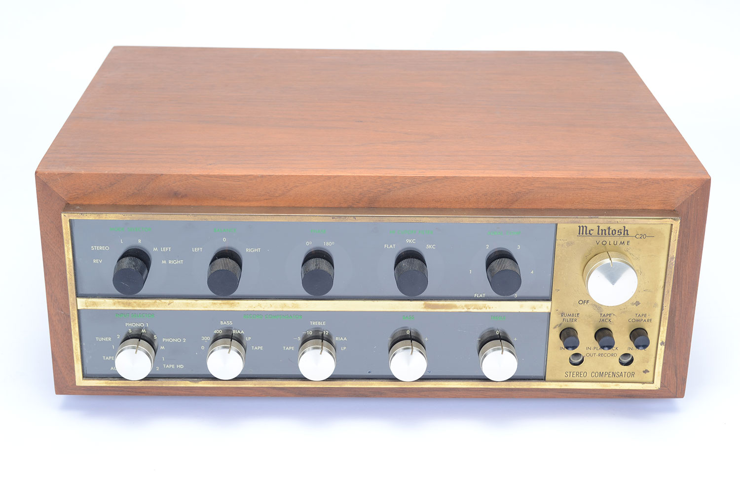
McIntosh C 20
Preamplifier -
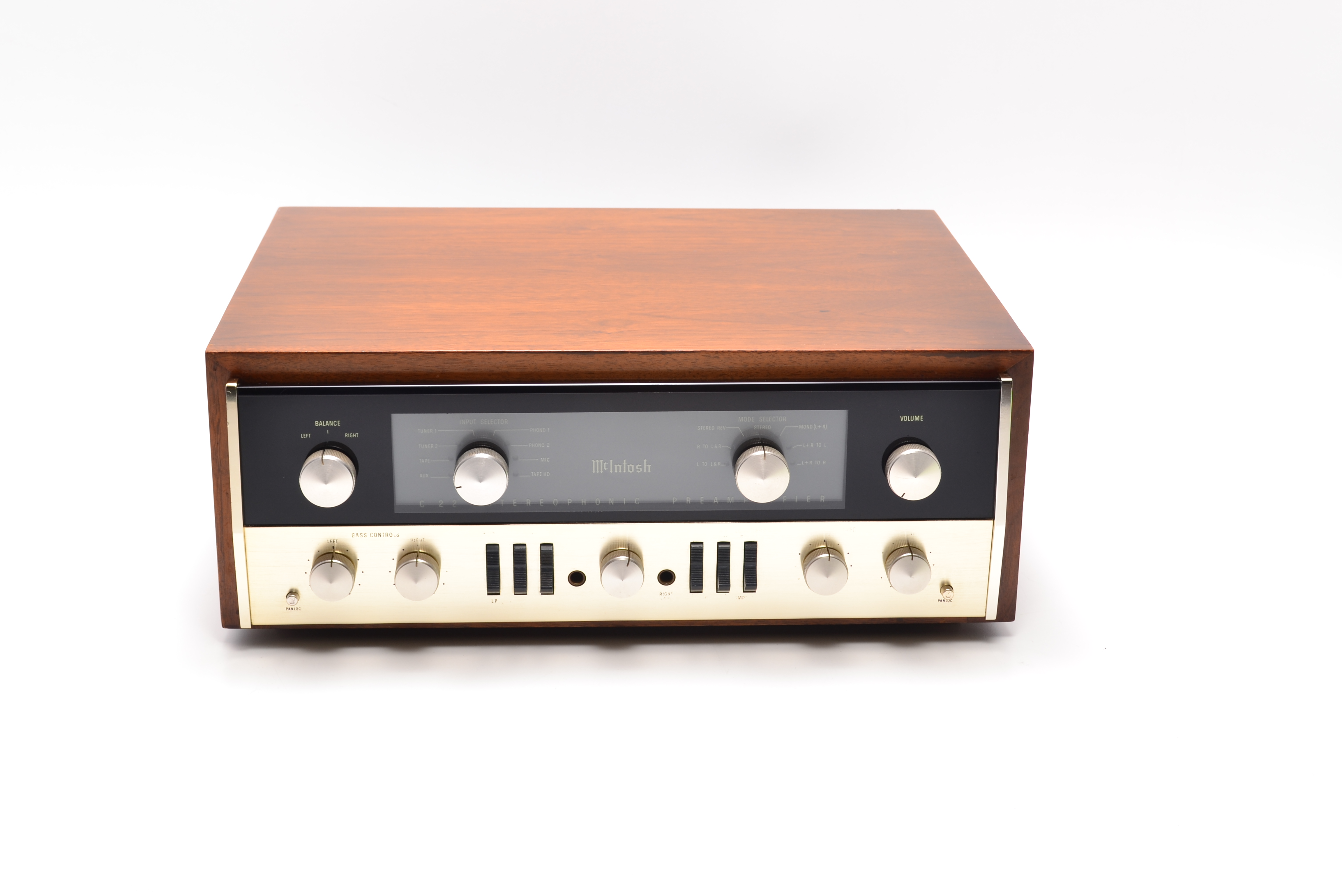
McIntosh C 22
Preamplifier -
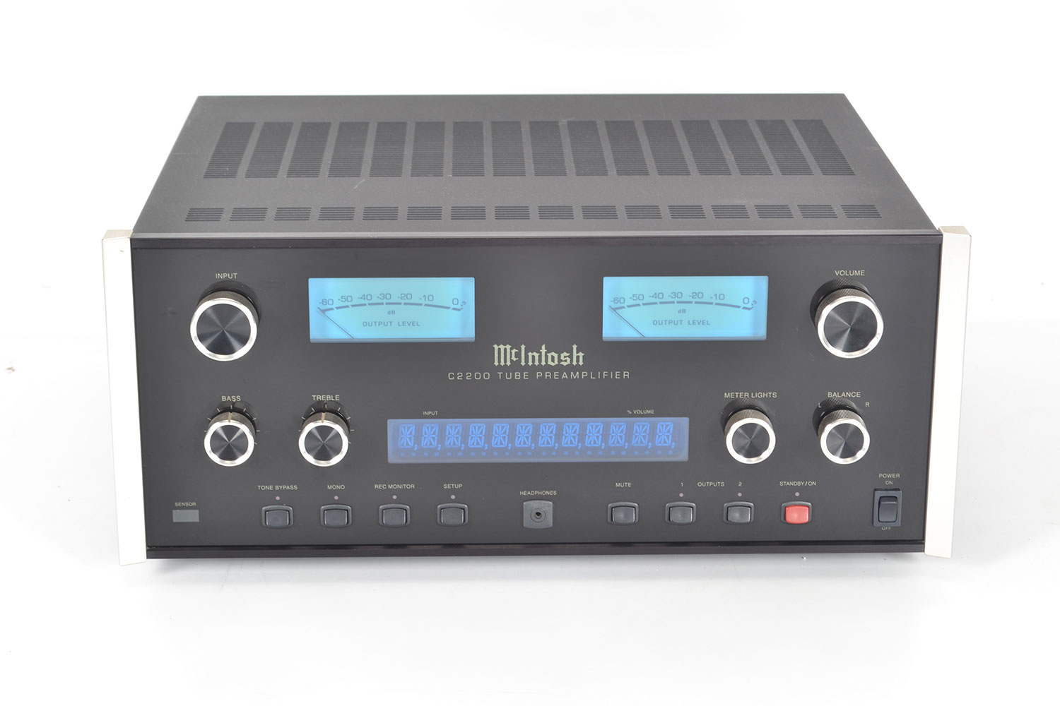
McIntosh C 2200
Preamplifier -
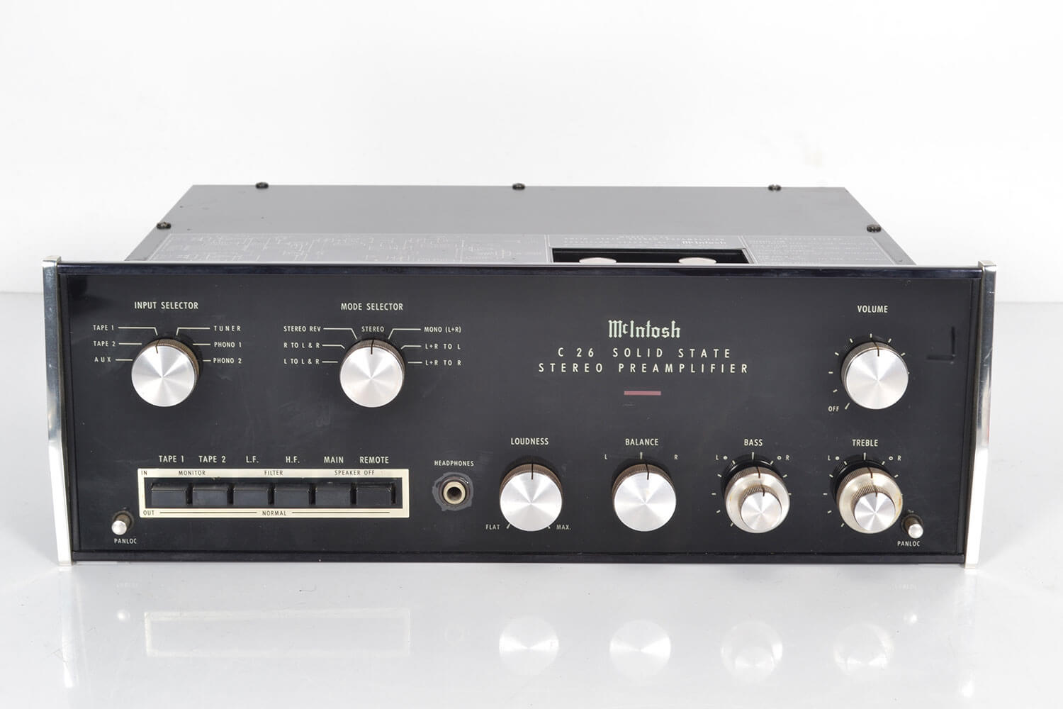
McIntosh C 26
Preamplifier -
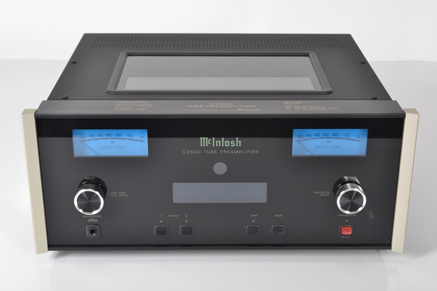
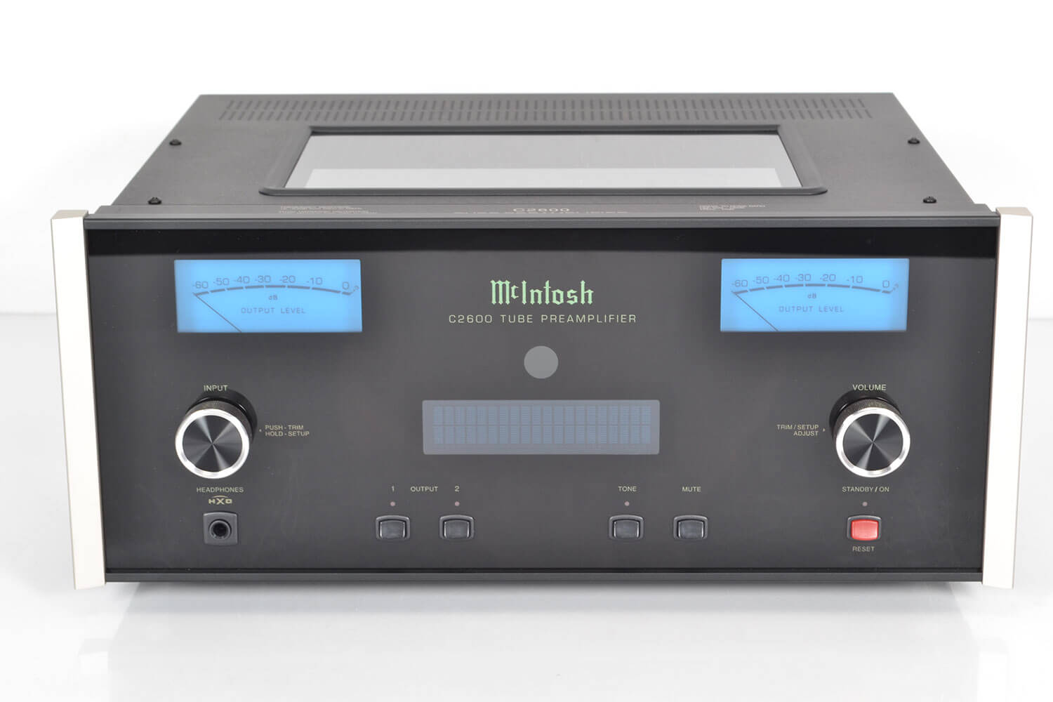
McIntosh C 2600
Preamplifier -
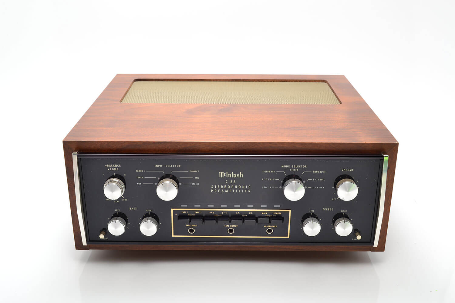
McIntosh C 28
Preamplifier -
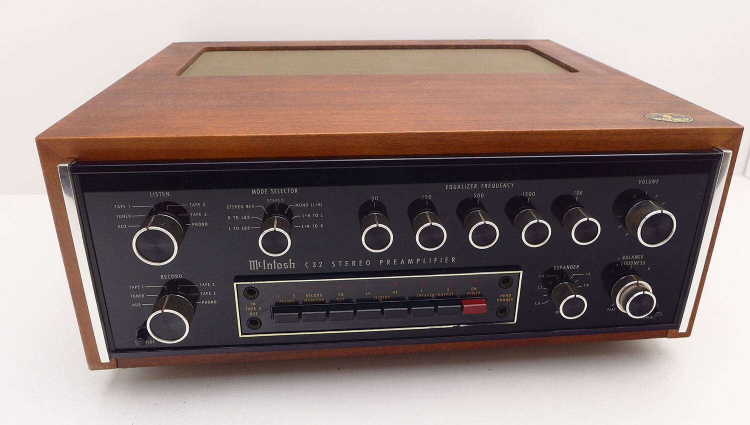
McIntosh C 32
Preamplifier -
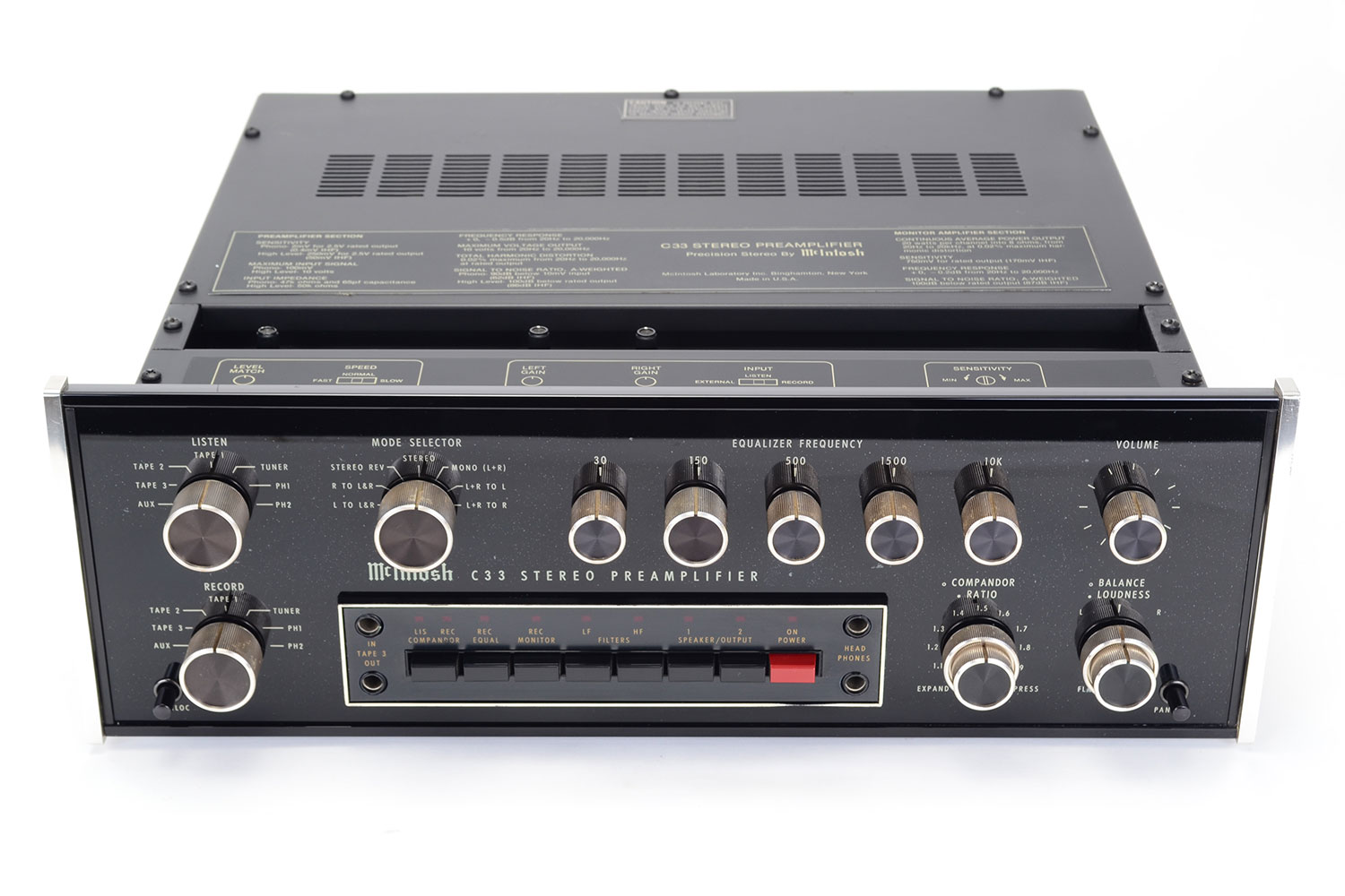
McIntosh C 33
Preamplifier -
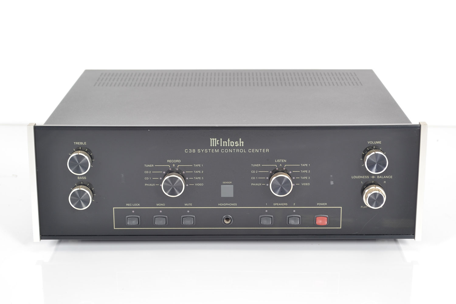
McIntosh C 38
Preamplifier -
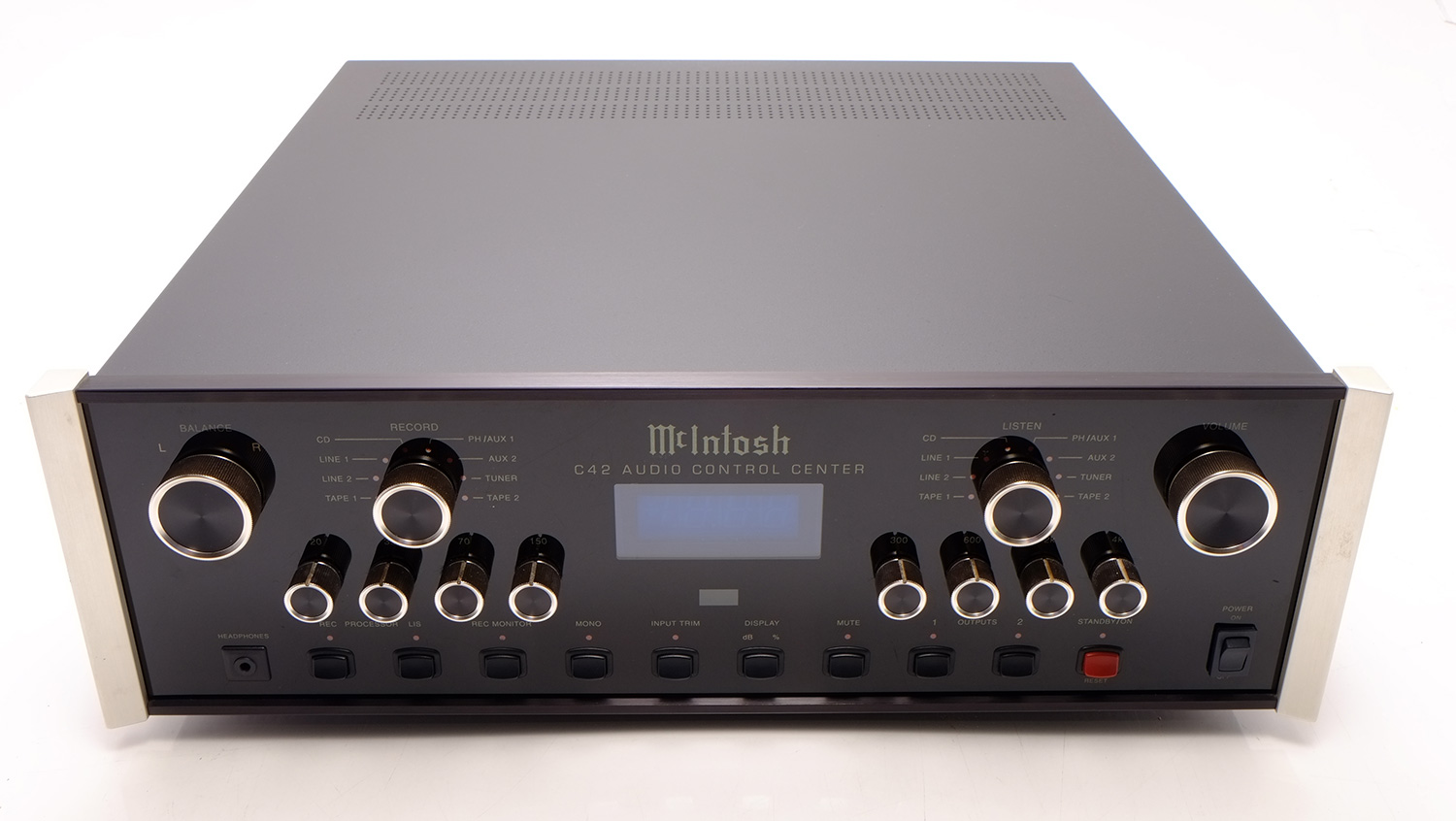
McIntosh C 42
Preamplifier -
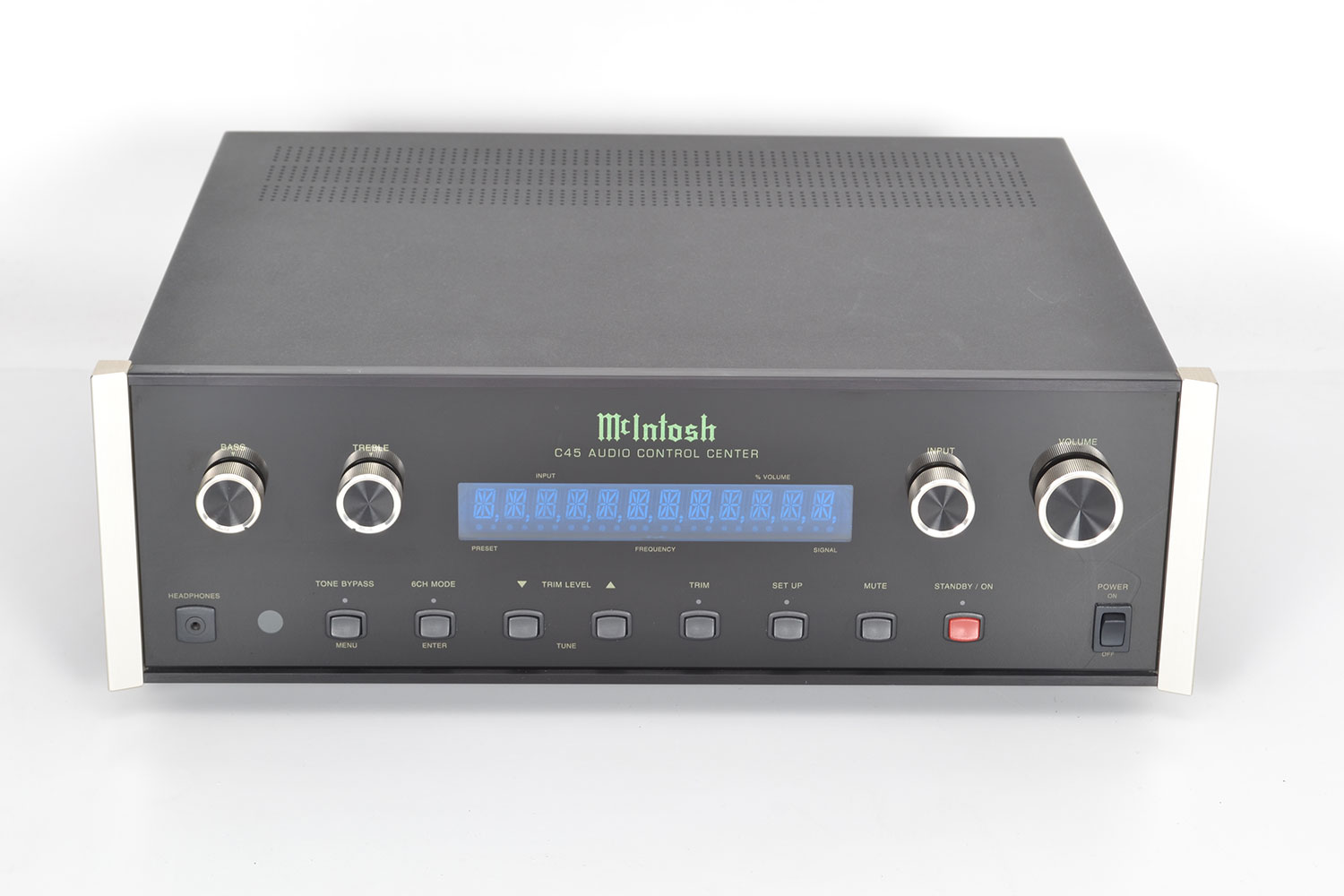
McIntosh C 45
Preamplifier -
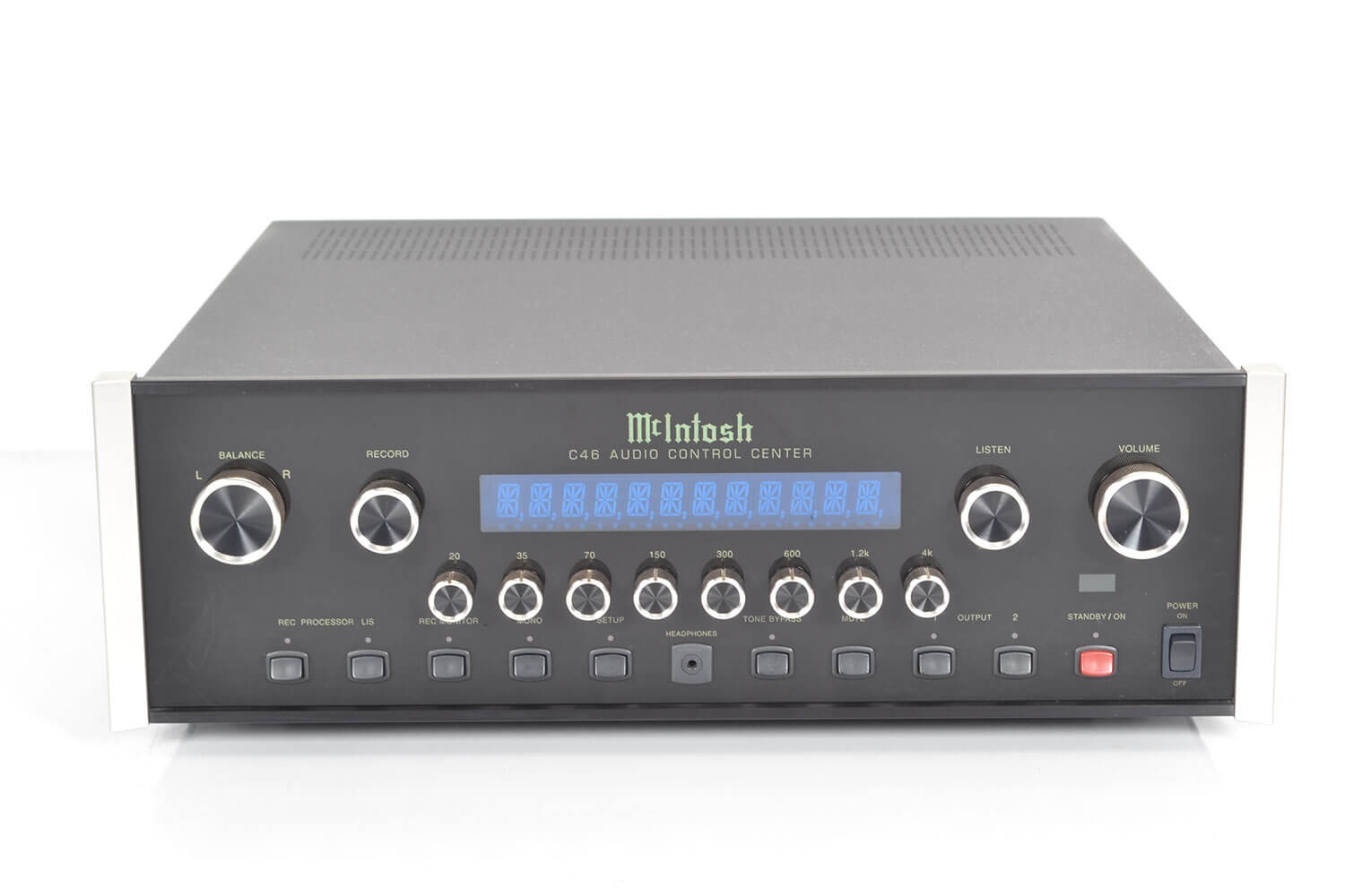
McIntosh C 46
Preamplifier -
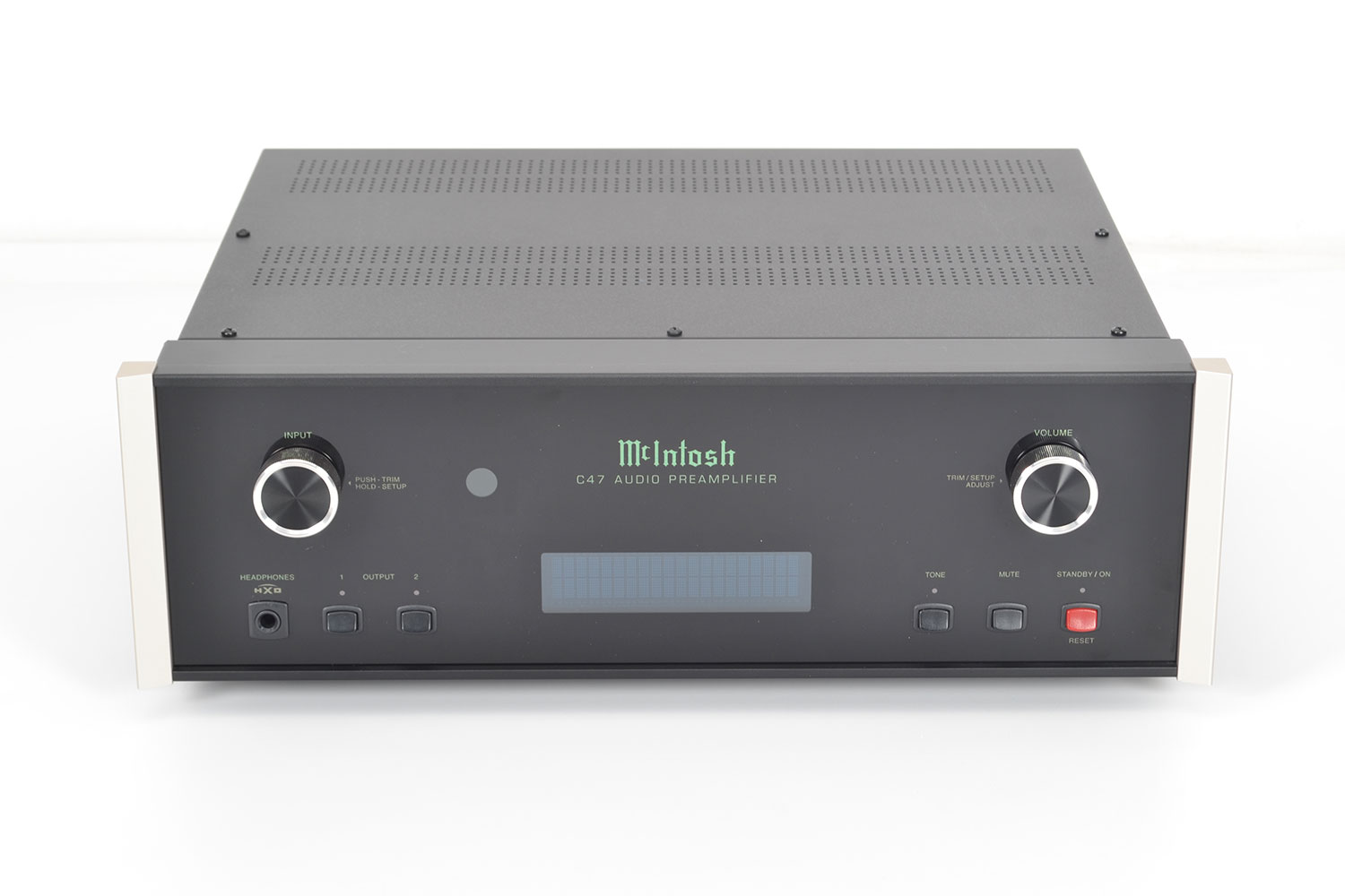
McIntosh C 47
Preamplifier -
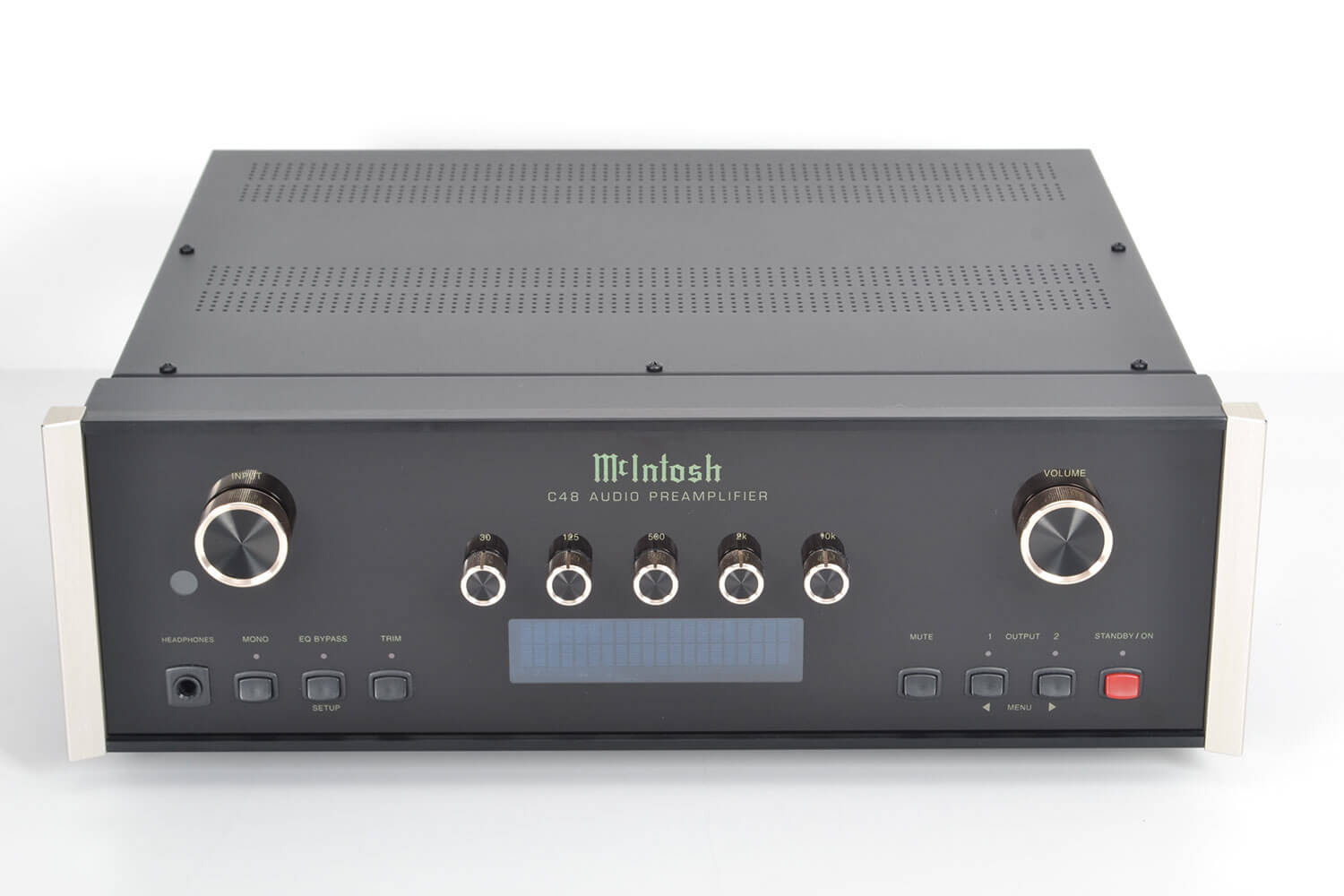
McIntosh C 48
Preamplifier -
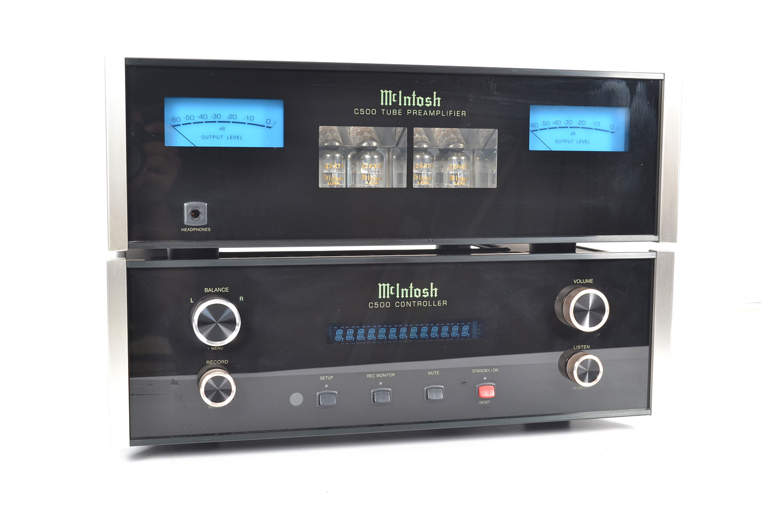
McIntosh C 500
Preamplifier -
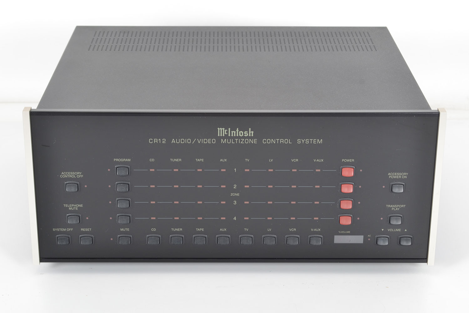
McIntosh CR 12
Preamplifier -
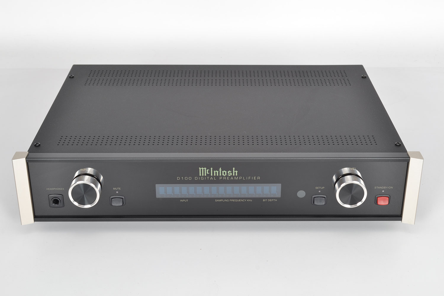
McIntosh D 100
Preamplifier -
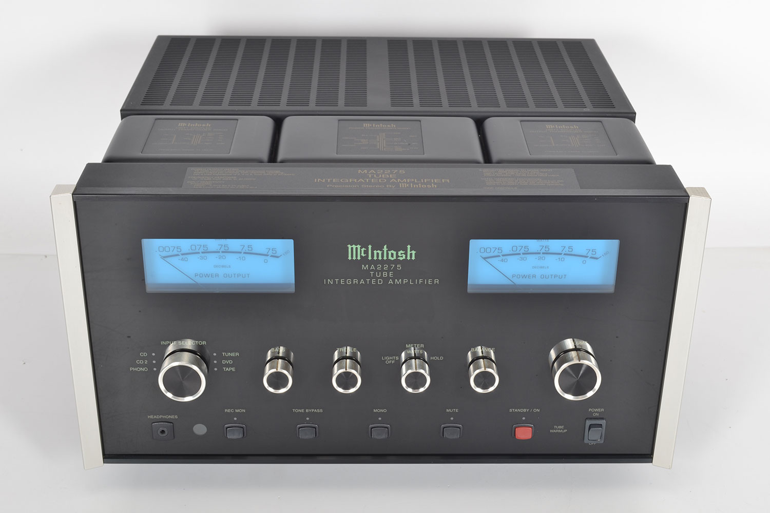
McIntosh MA 2275
Integrated amplifier -
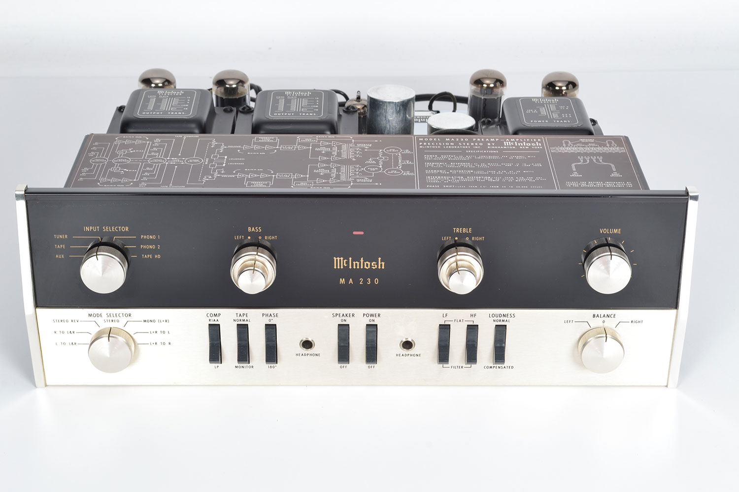
McIntosh MA 230
Integrated amplifier -
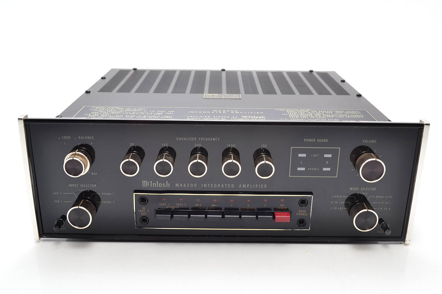
McIntosh MA 6200
Integrated amplifier -
McIntosh MA 6300
Integrated amplifier -
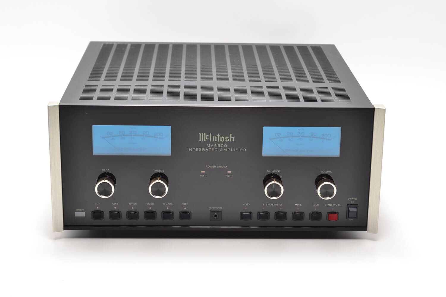
McIntosh MA 6500
Integrated amplifier -
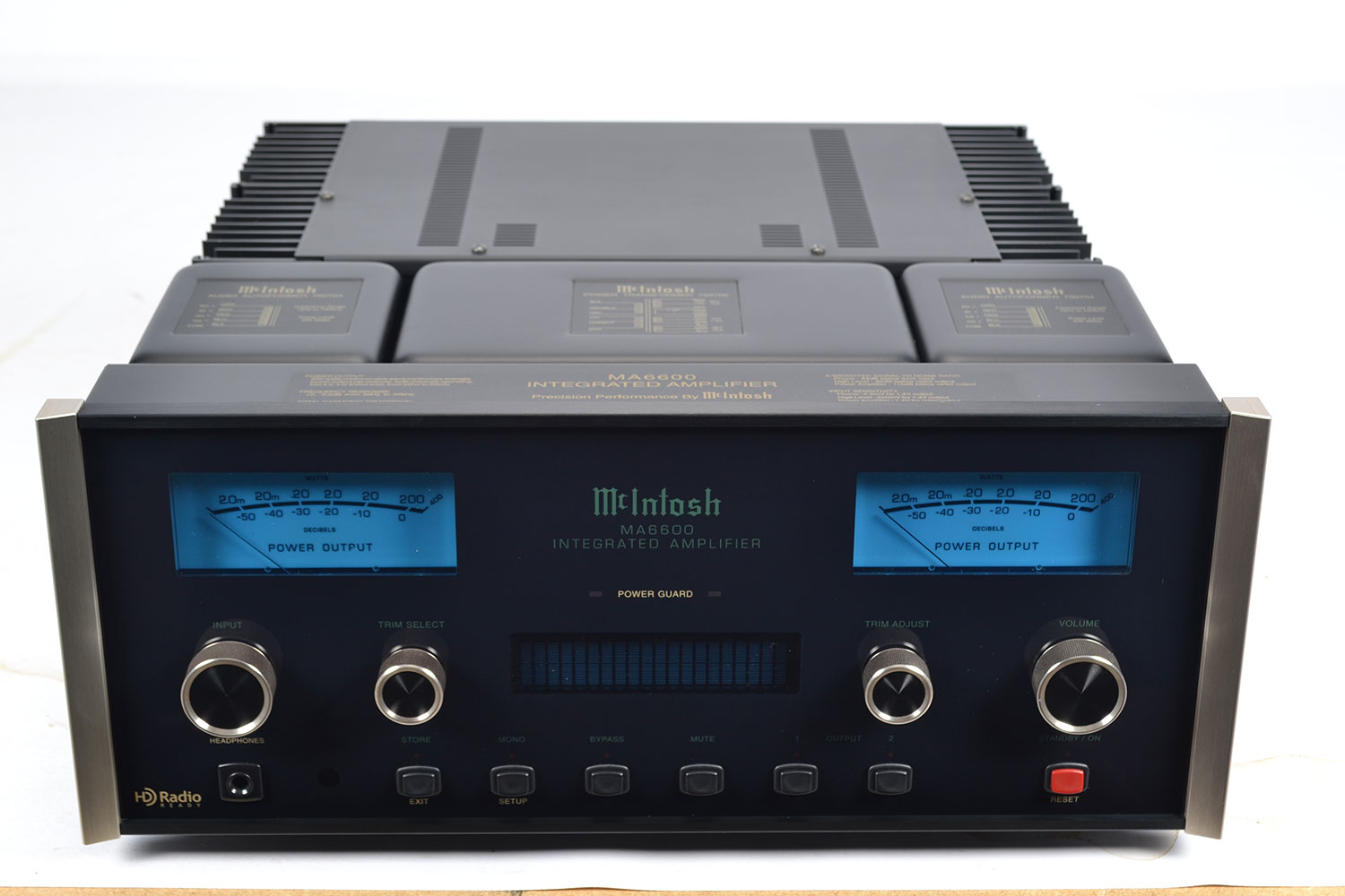
McIntosh MA 6600
Integrated amplifier -
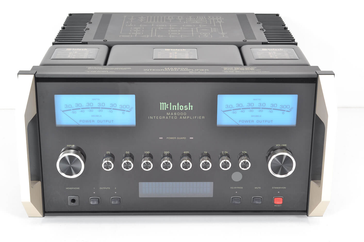
McIntosh MA 8000
Integrated amplifier -
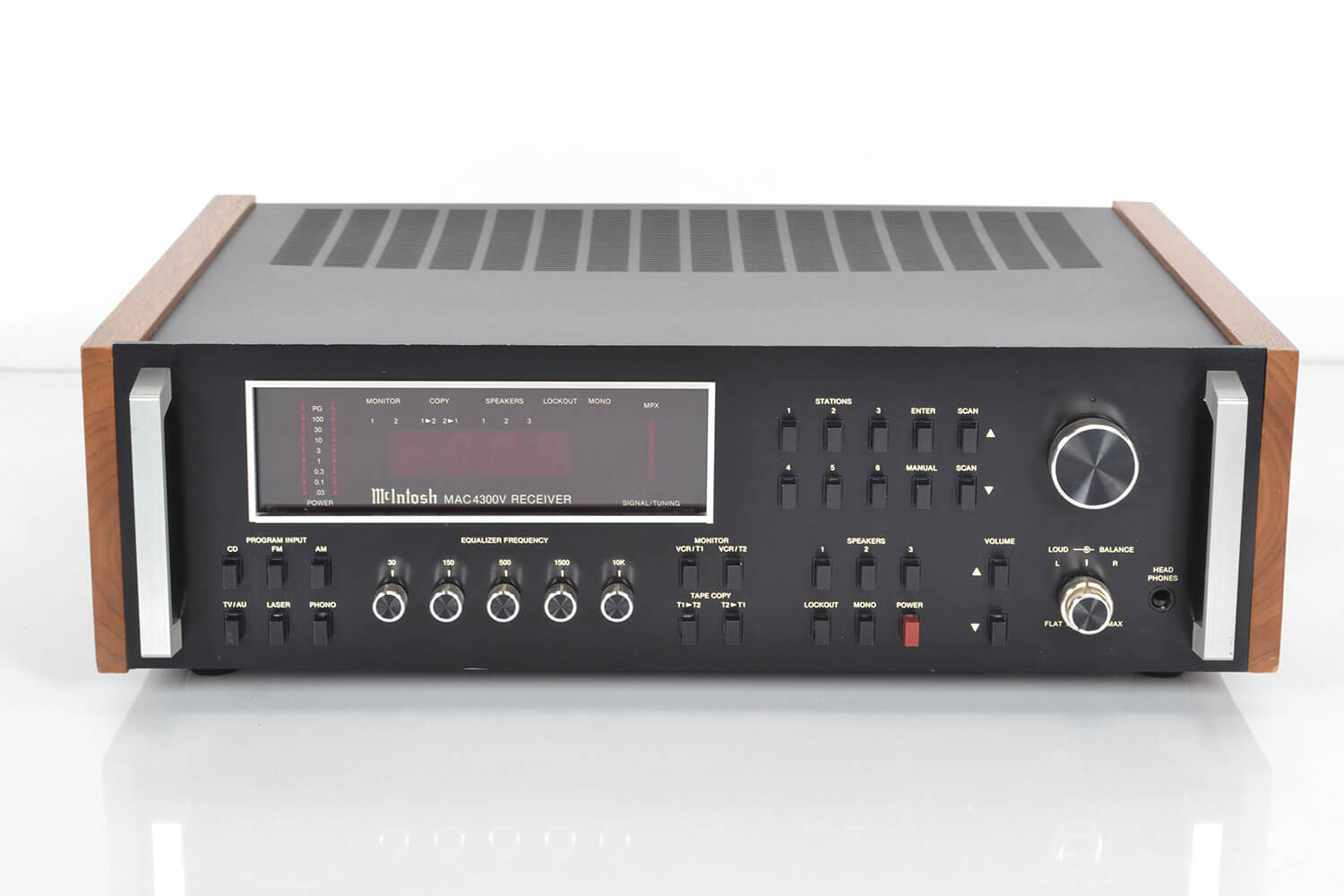
McIntosh MAC 4300V
Receiver -
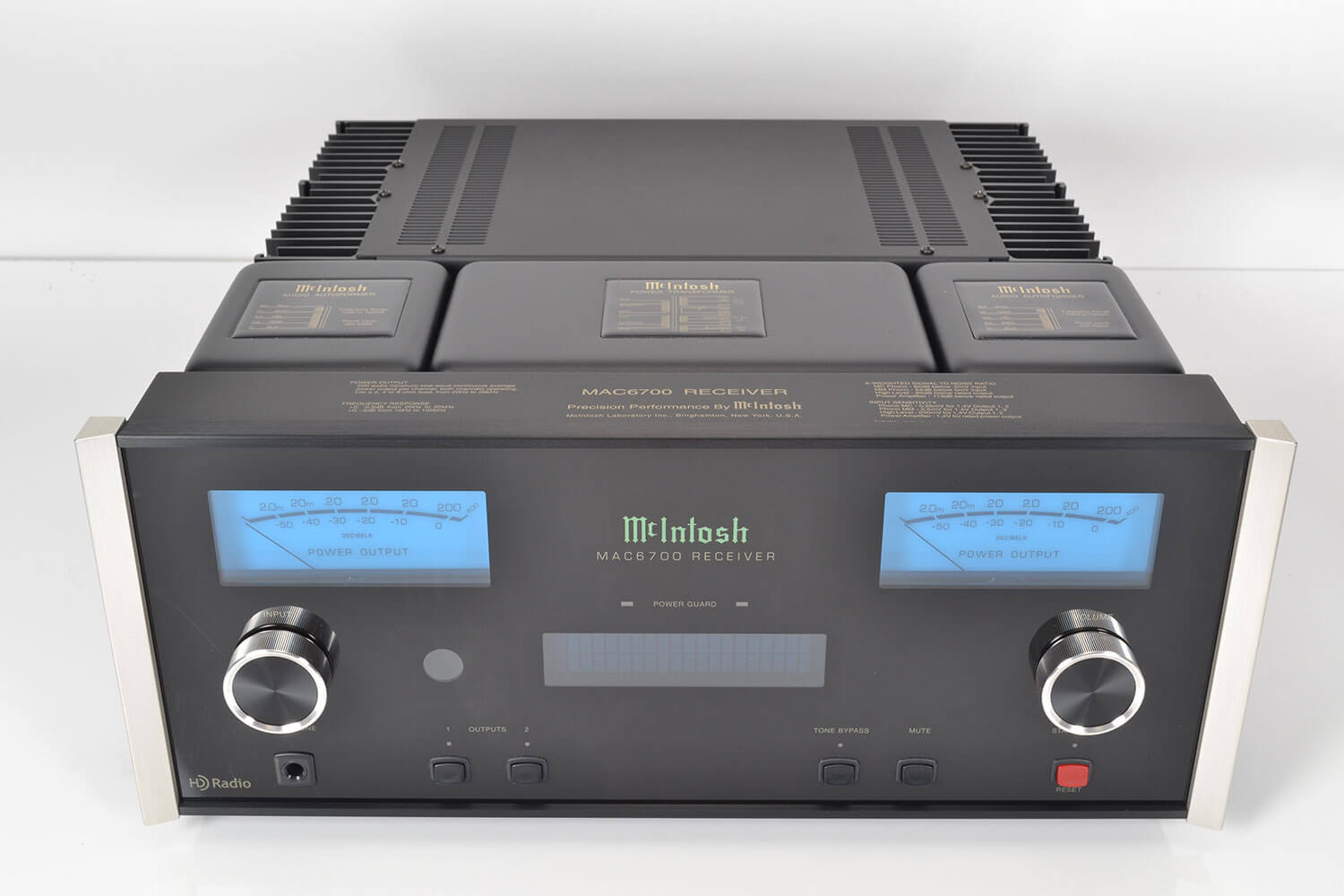
McIntosh MAC 6700
Receiver -
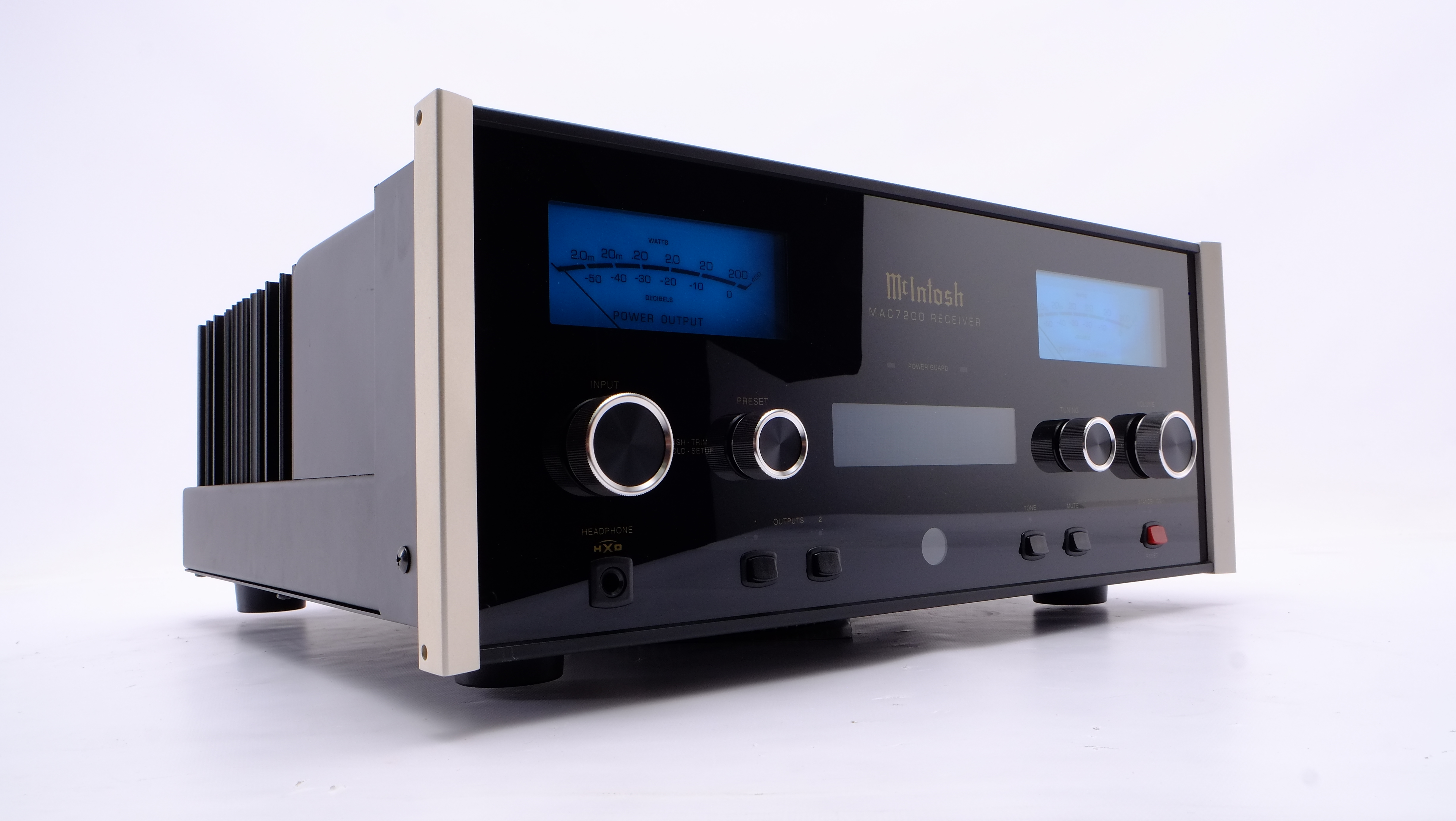
McIntosh MAC 7200
Receiver -
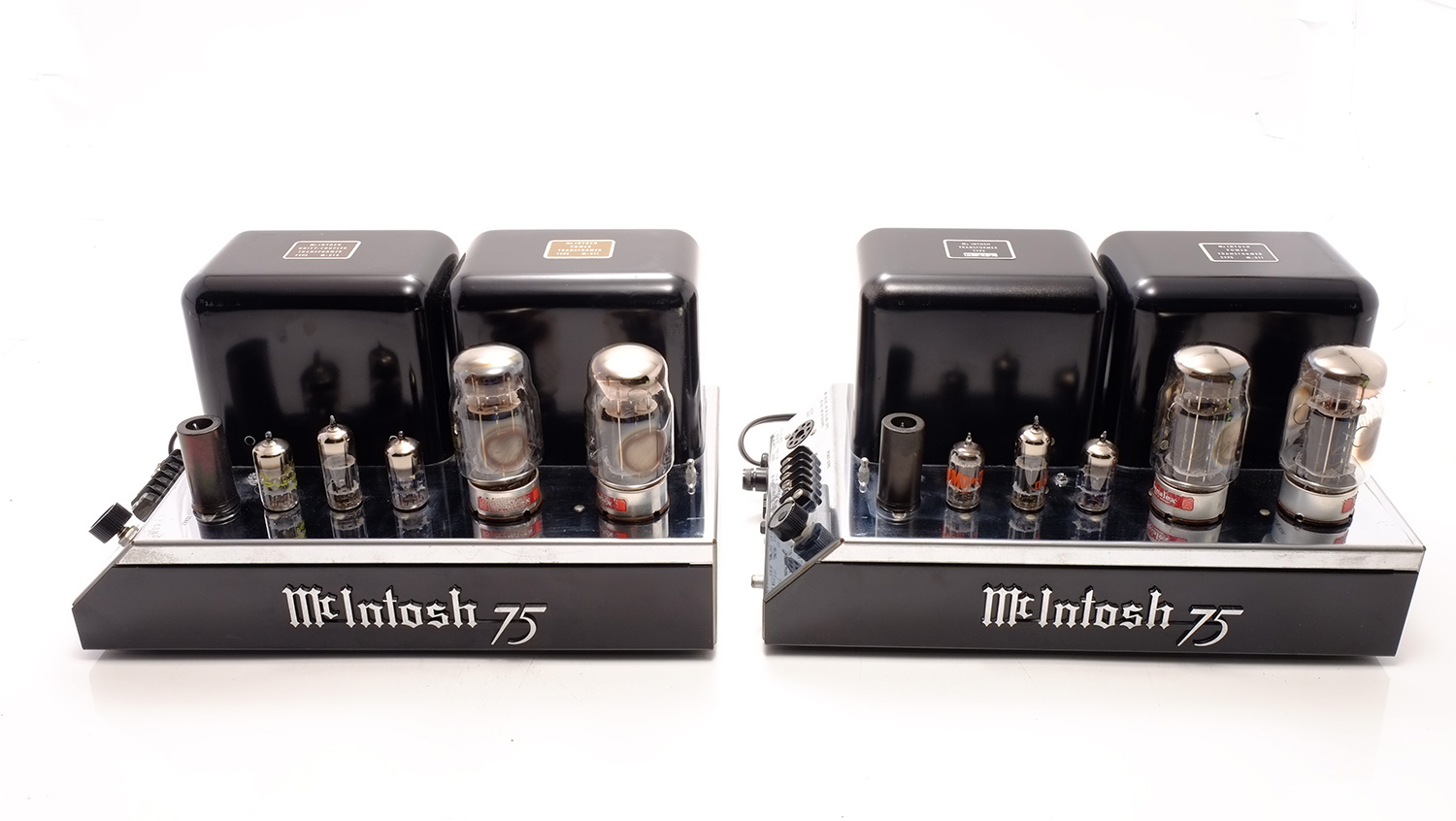
McIntosh MC 75
Amplifier -
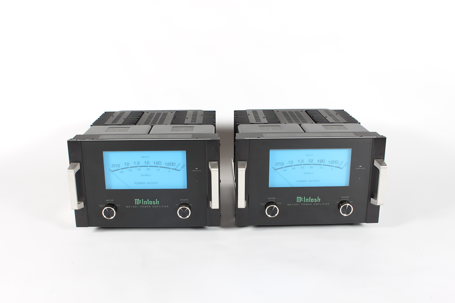
McIntosh MC 1201
Amplifier -

McIntosh MC 122
Amplifier -
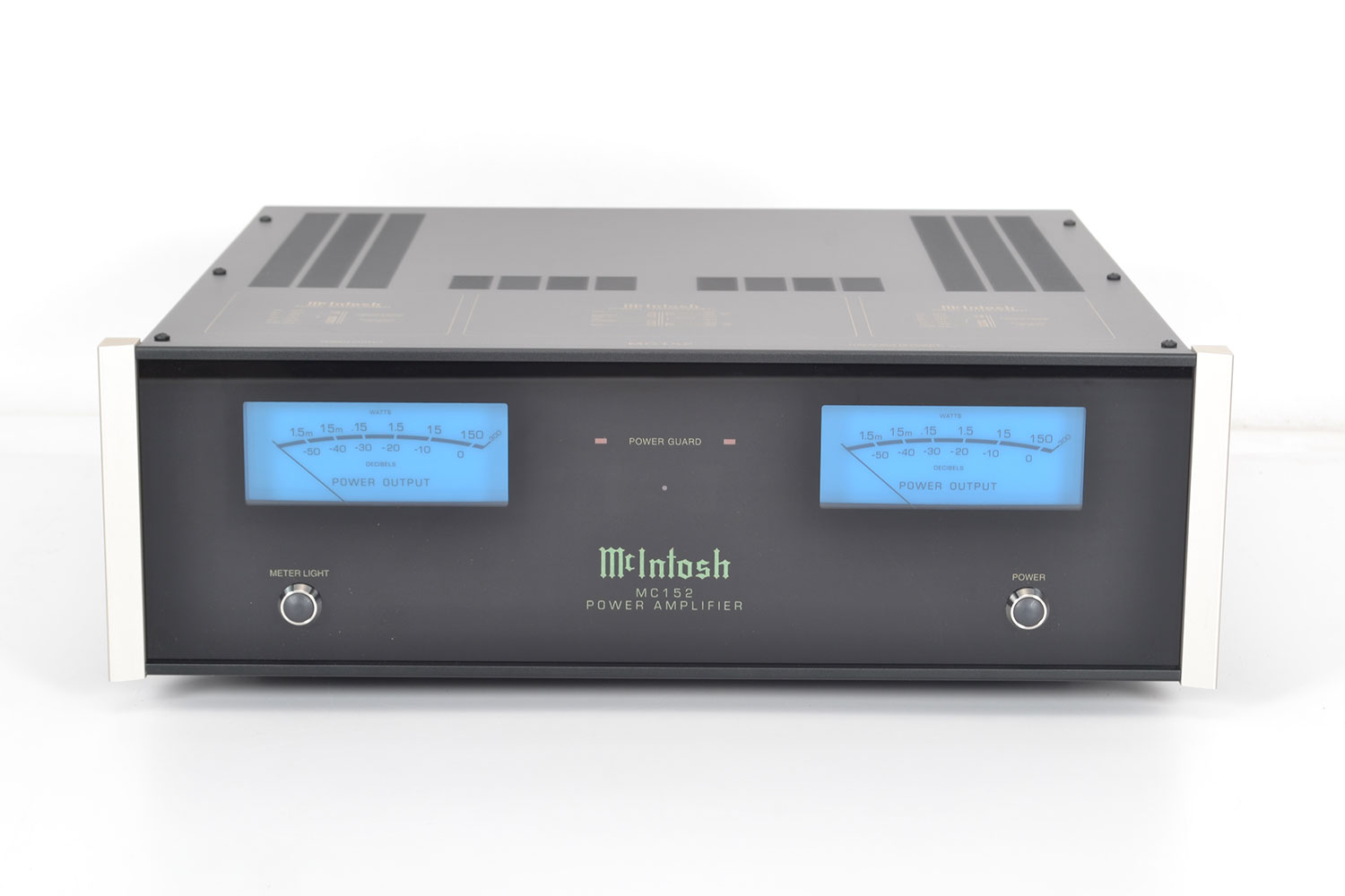
McIntosh MC 152
Amplifier -
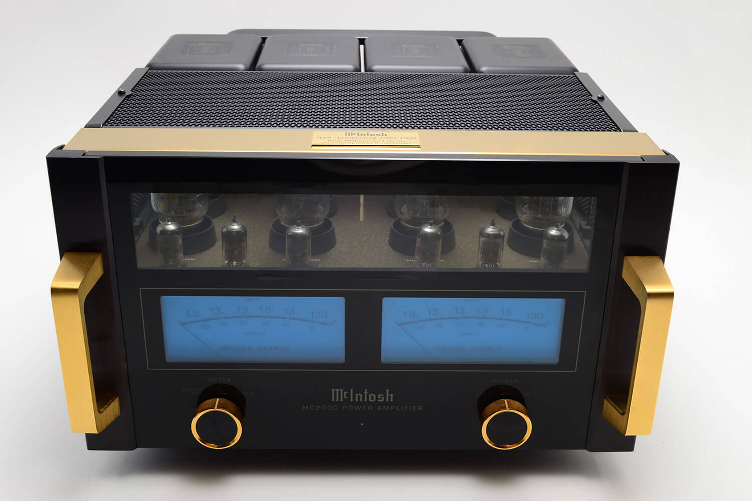
McIntosh MC 2000
Amplifier -
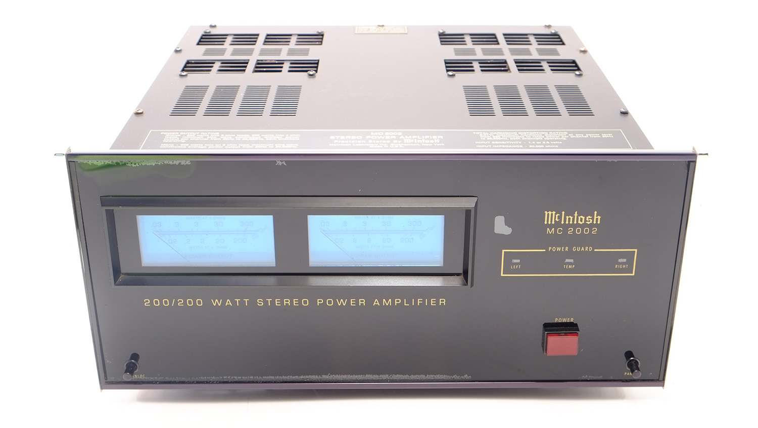
McIntosh MC 2002
Amplifier -
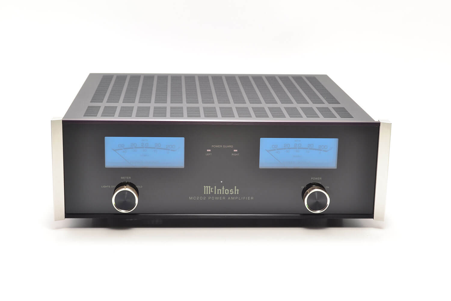
McIntosh MC 202
Amplifier -
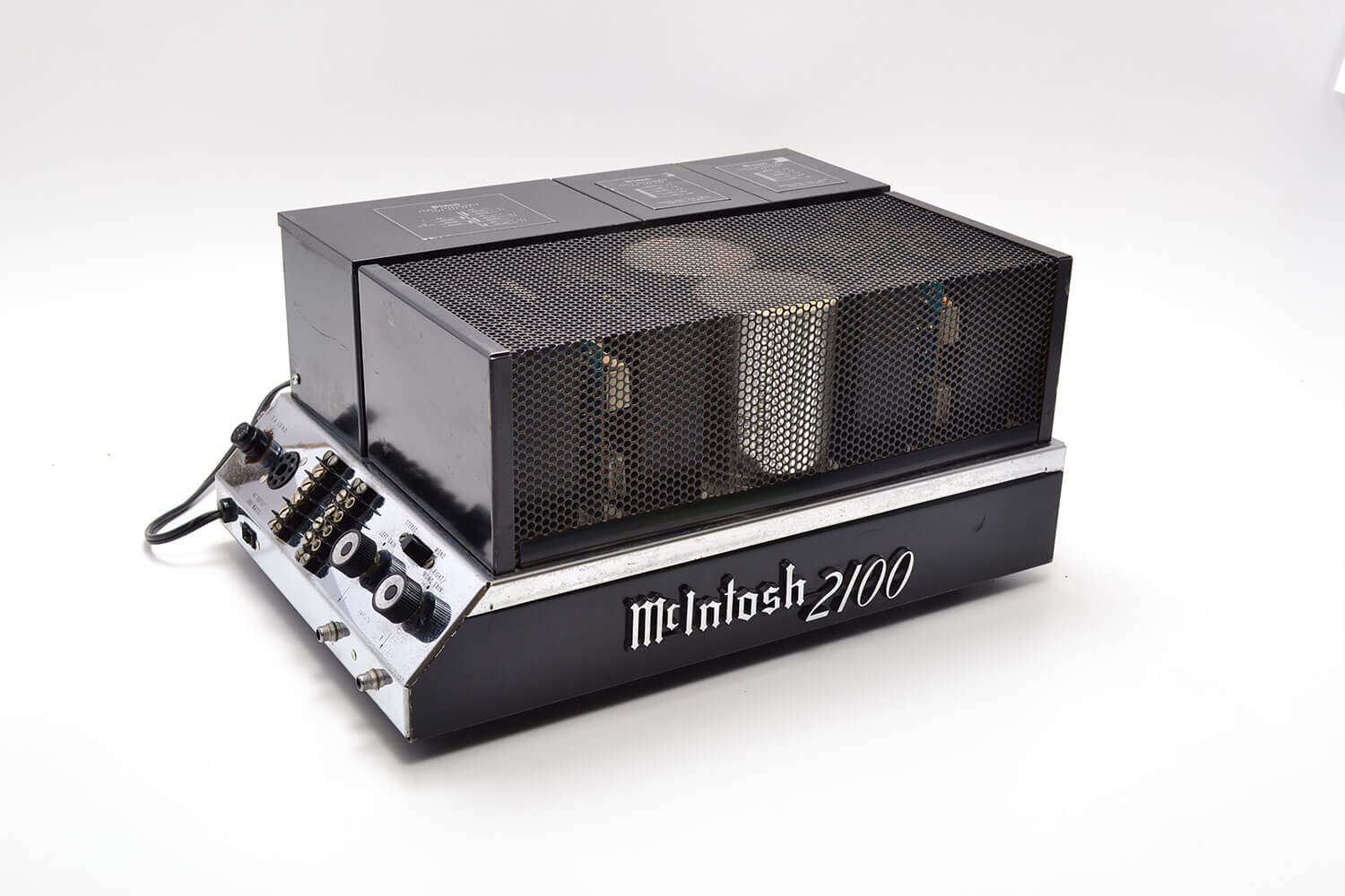
McIntosh MC 2100
Amplifier -
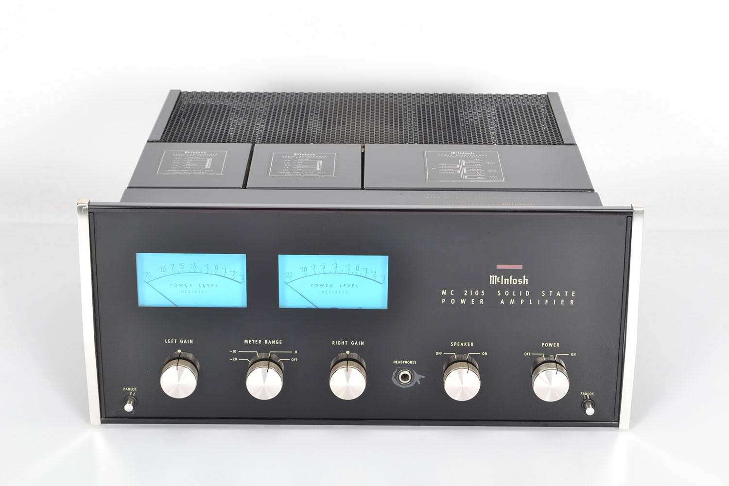
McIntosh MC 2105
Amplifier -
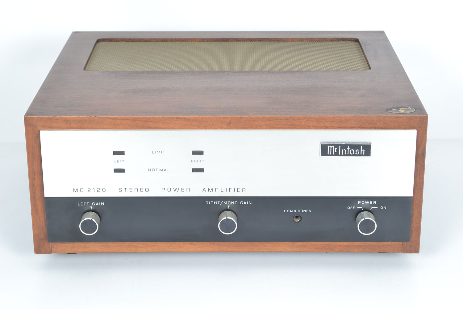
McIntosh MC 2120
Amplifier -
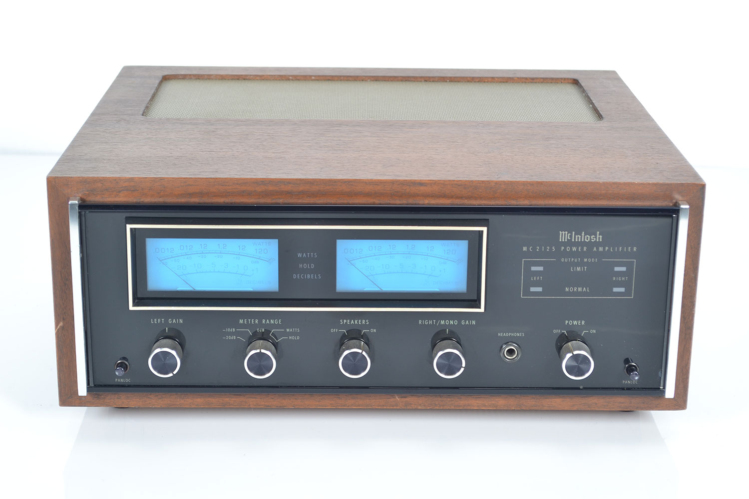
McIntosh MC 2125
Amplifier -
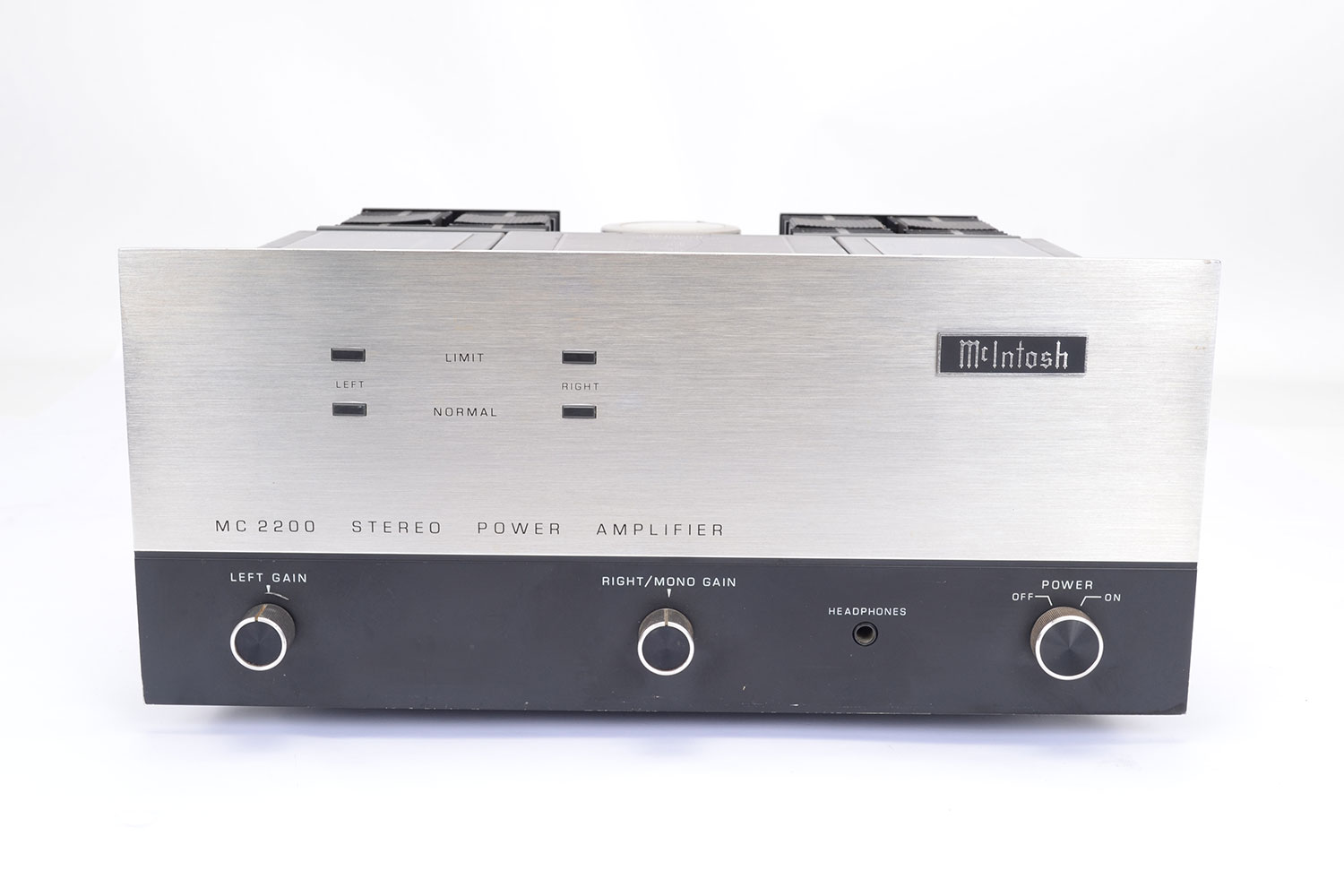
McIntosh MC 2200
Amplifier -
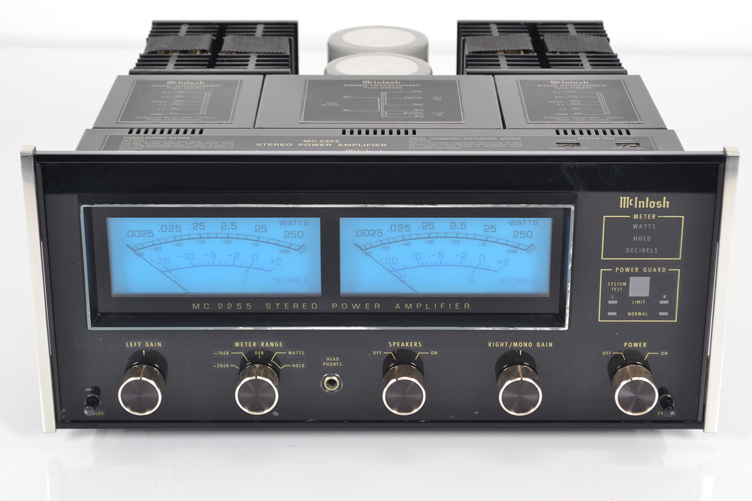
McIntosh MC 2255
Amplifier -
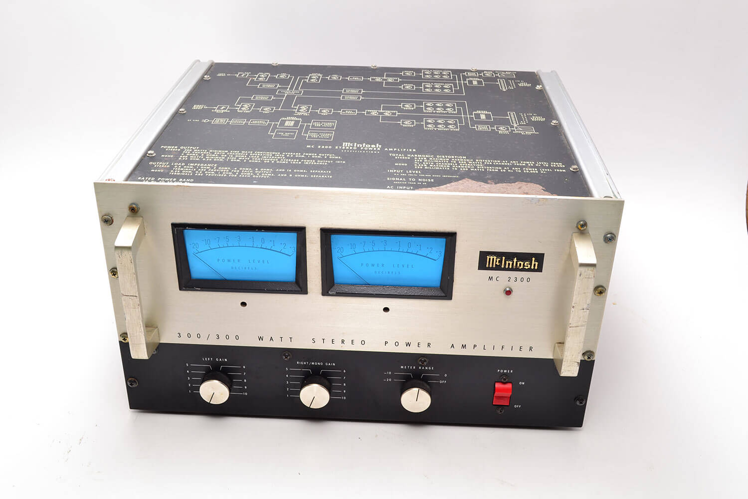
McIntosh MC 2300
Amplifier -
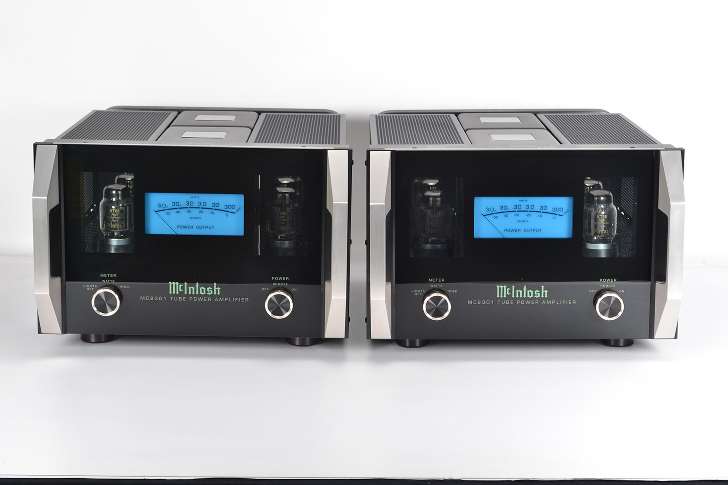
McIntosh MC 2301
Amplifier -
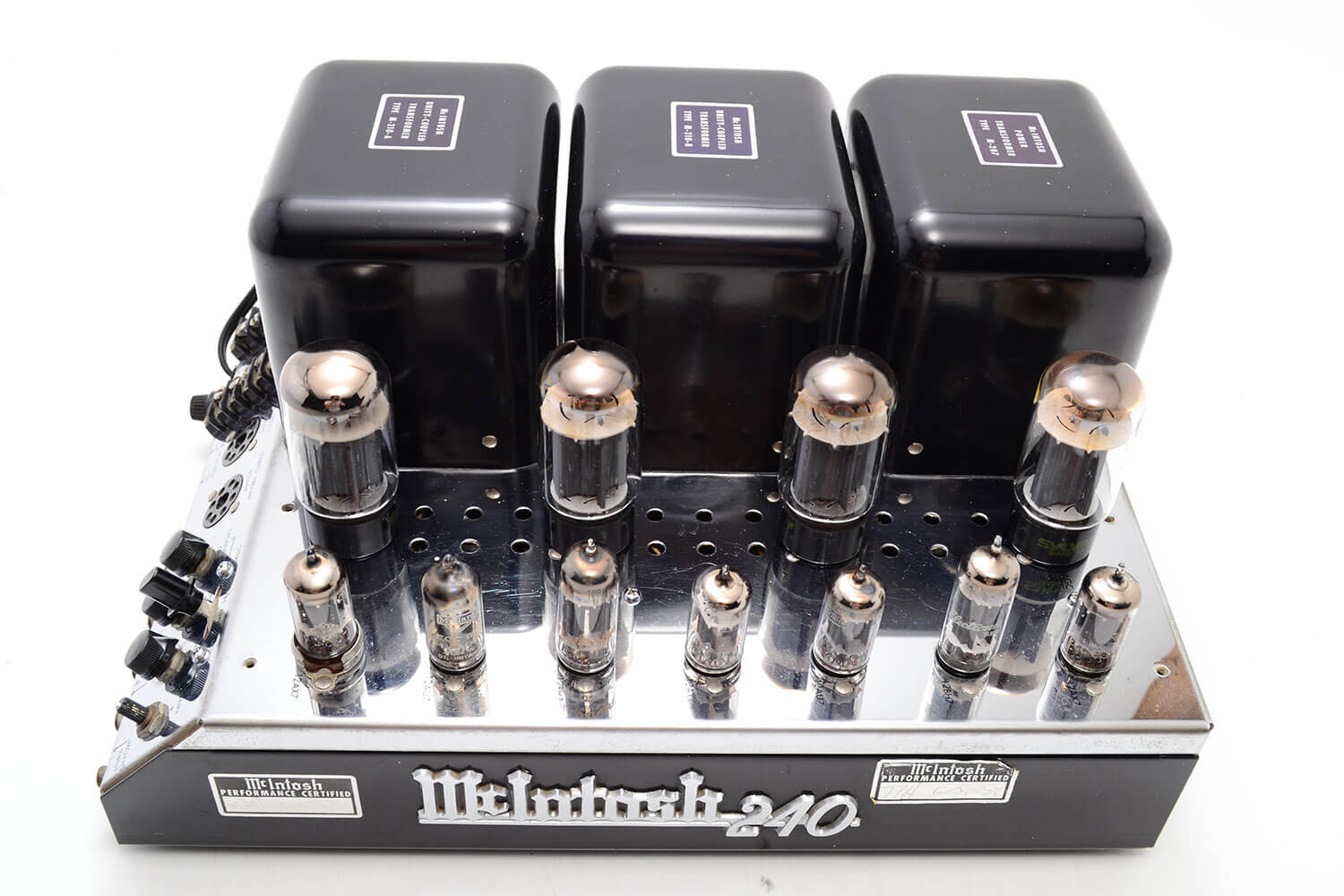
McIntosh MC 240
Amplifier -
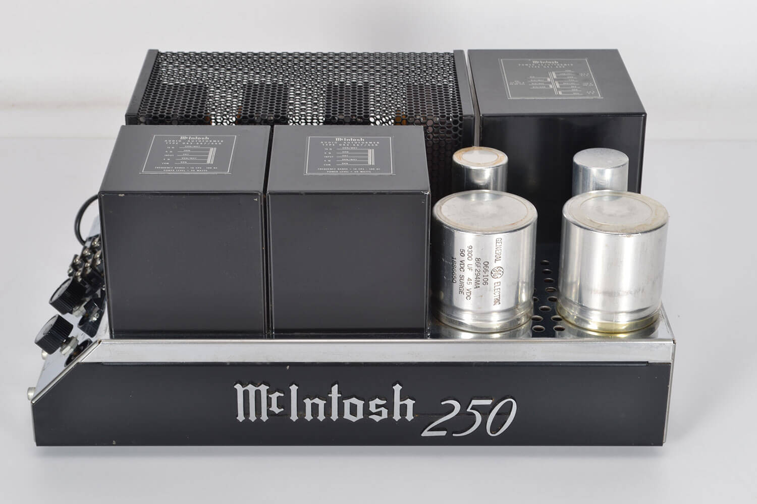
McIntosh MC 250
Amplifier -
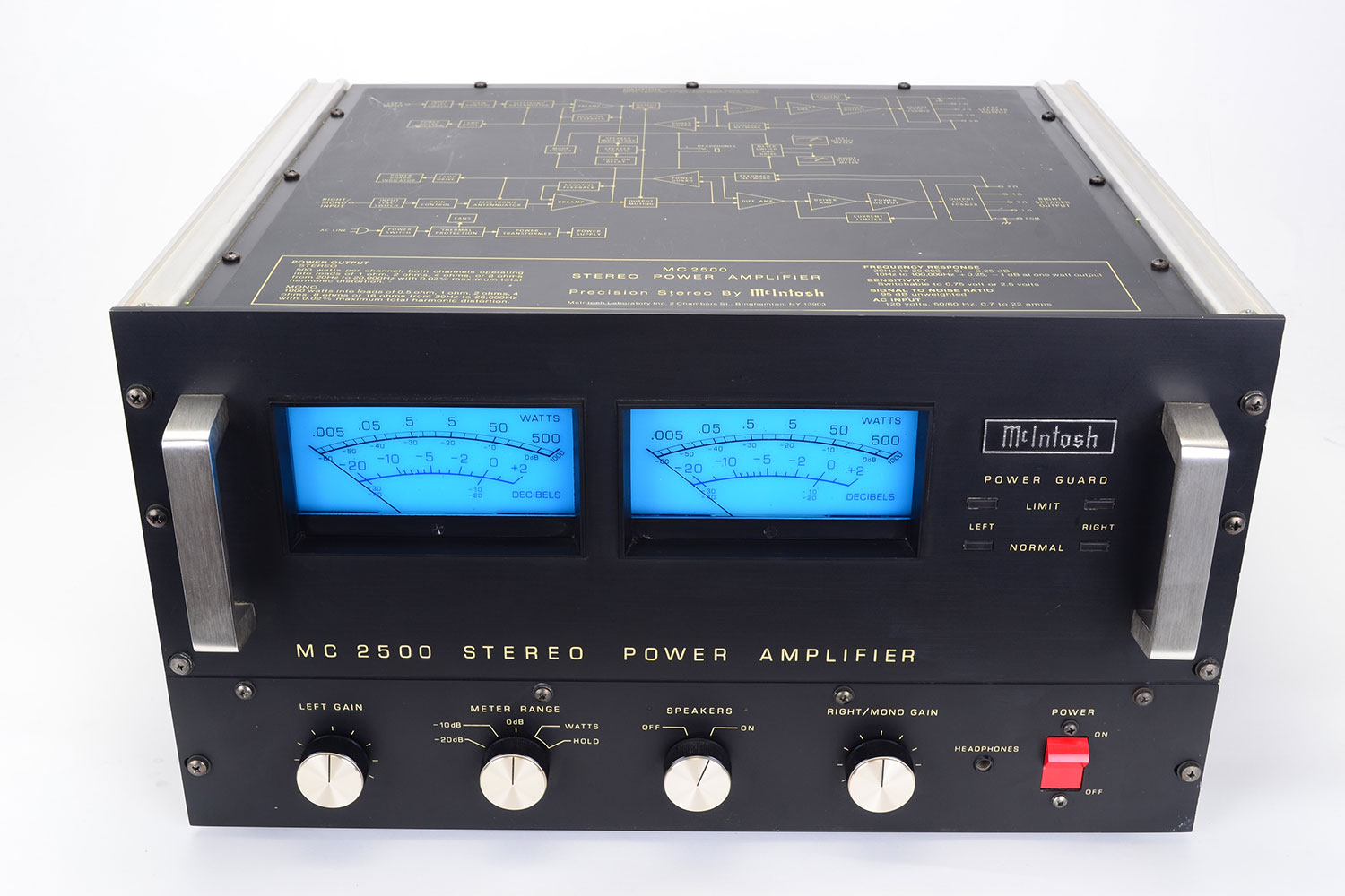
McIntosh MC 2500
Amplifier -
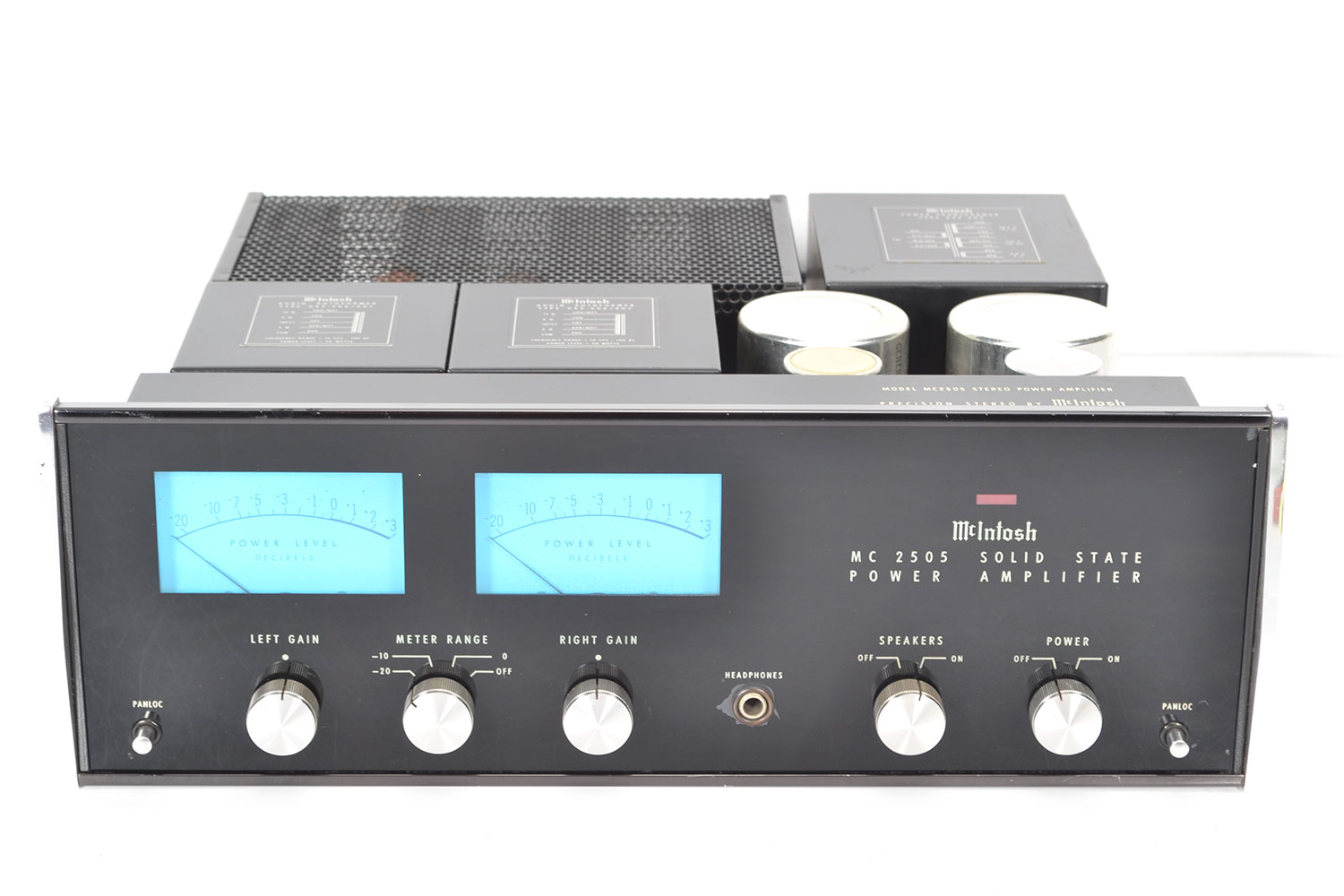
McIntosh MC 2505
Amplifier -
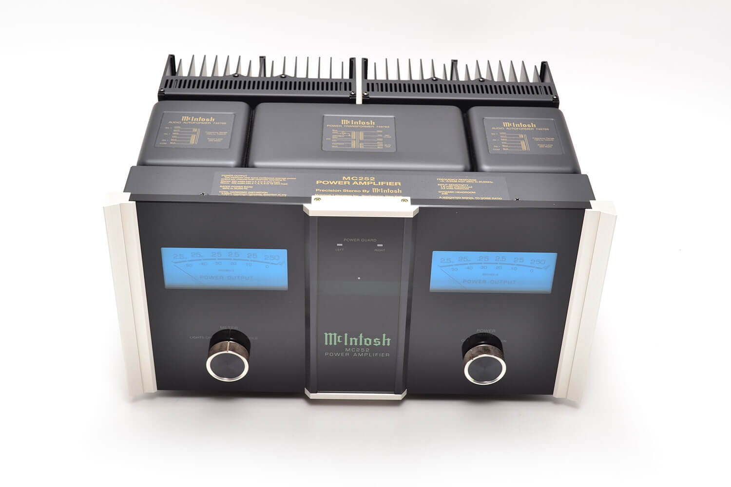
McIntosh MC 252
Amplifier -
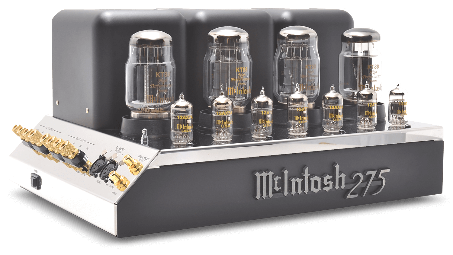
McIntosh MC 275
Amplifier -
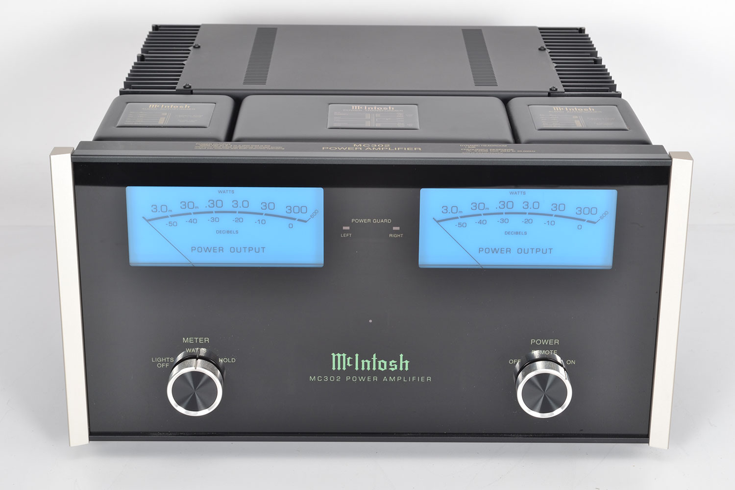
McIntosh MC 302
Amplifier -
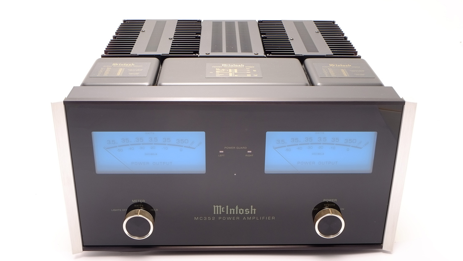
McIntosh MC 352
Amplifier -
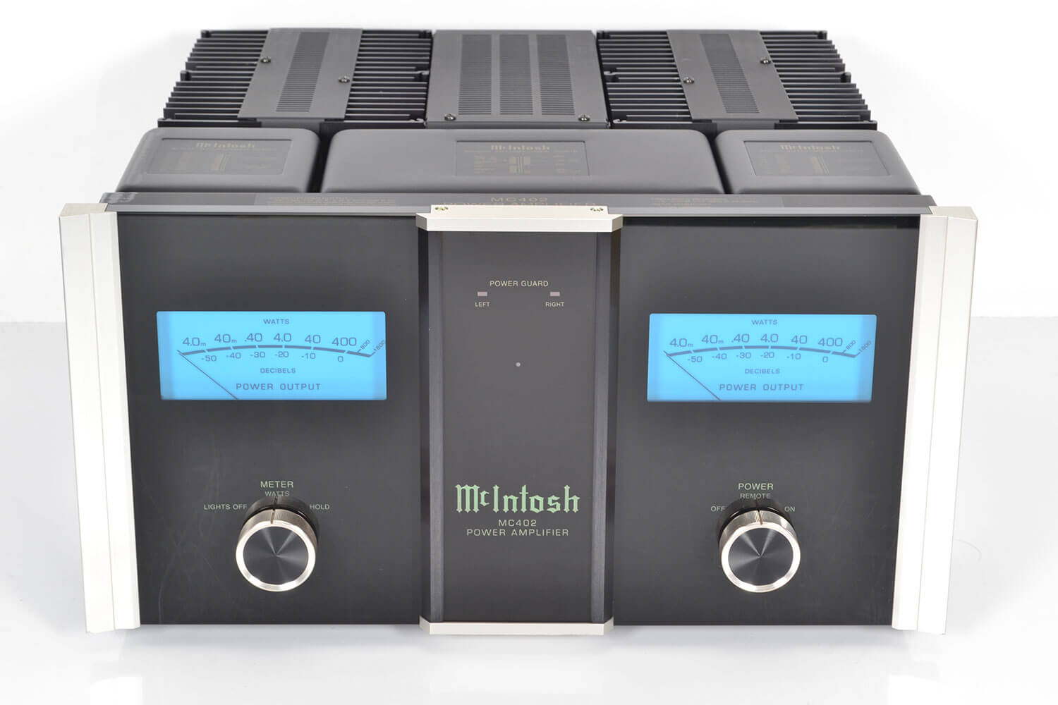
McIntosh MC 402
Amplifier -
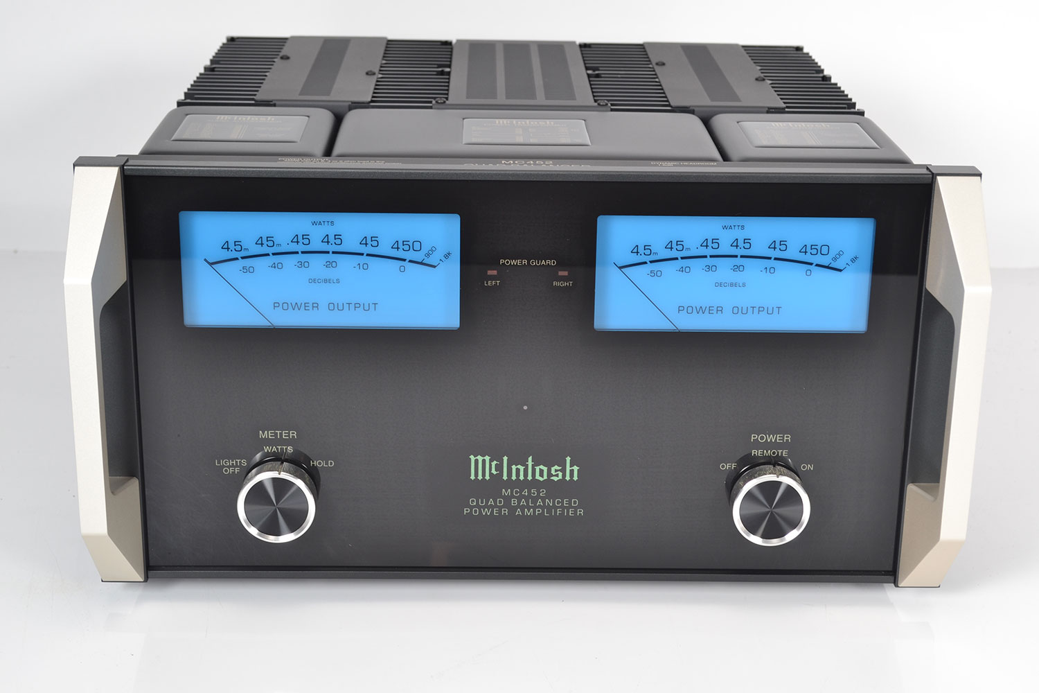
McIntosh MC 452
Amplifier -
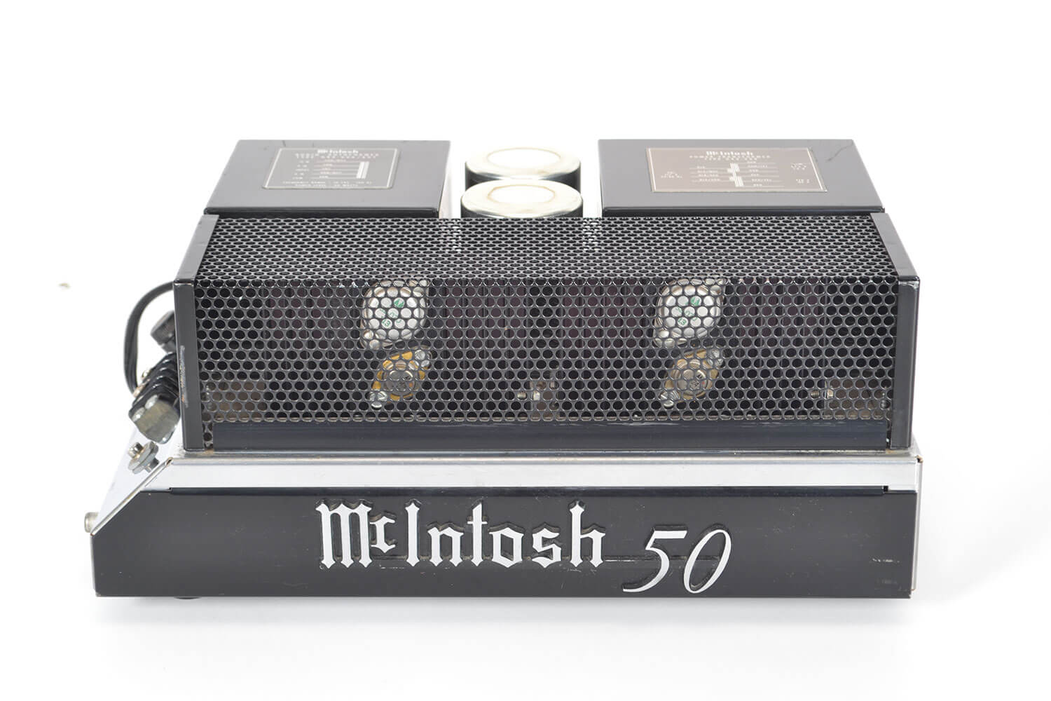
McIntosh MC 50
Amplifier -
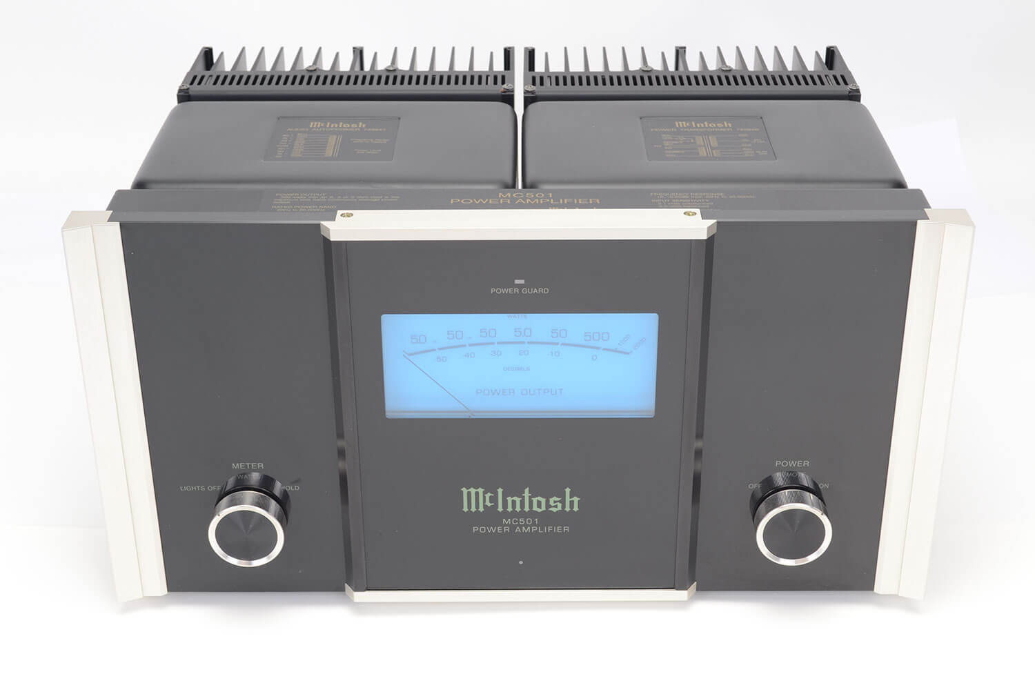
McIntosh MC 501
Amplifier -
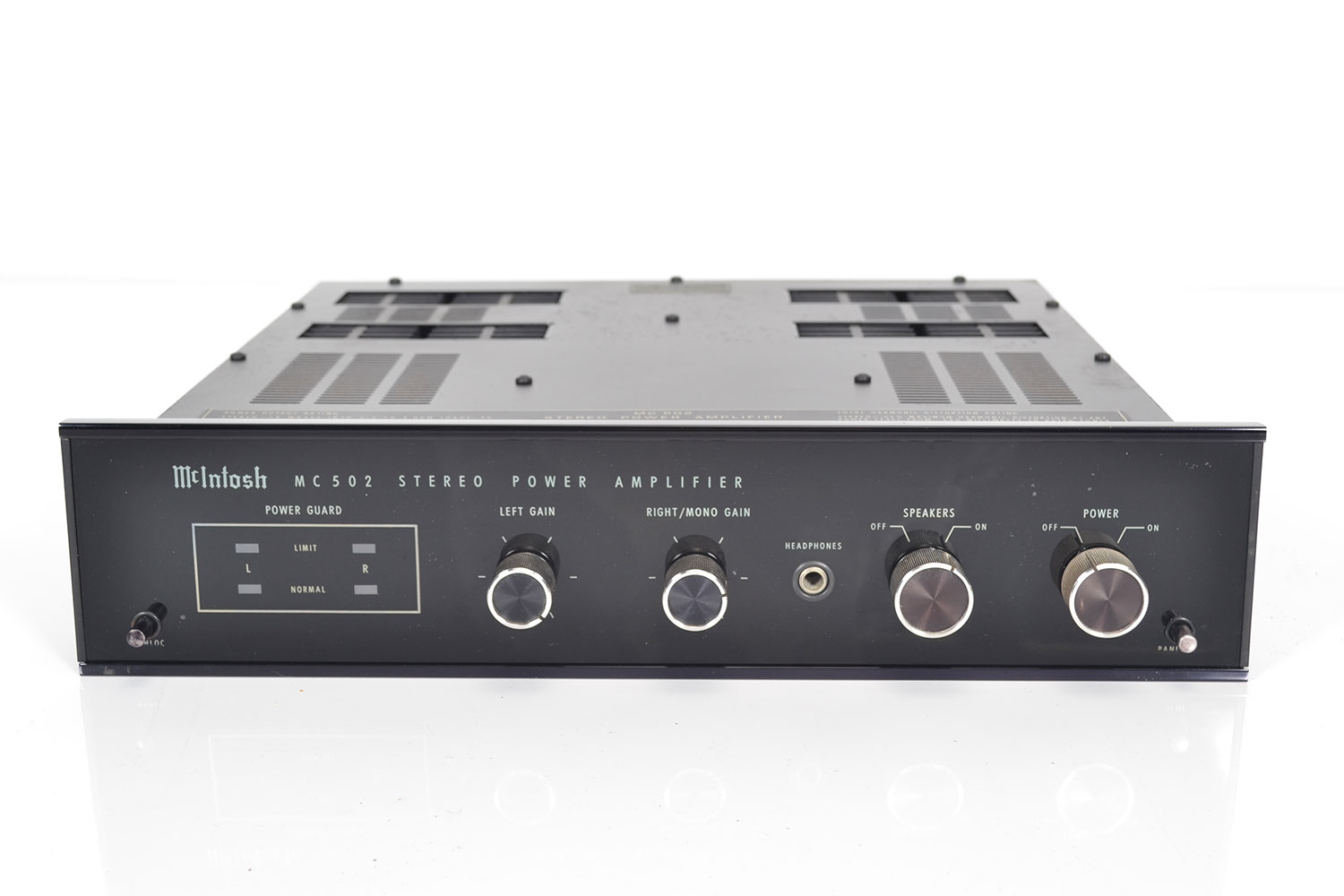
McIntosh MC 502
Amplifier -
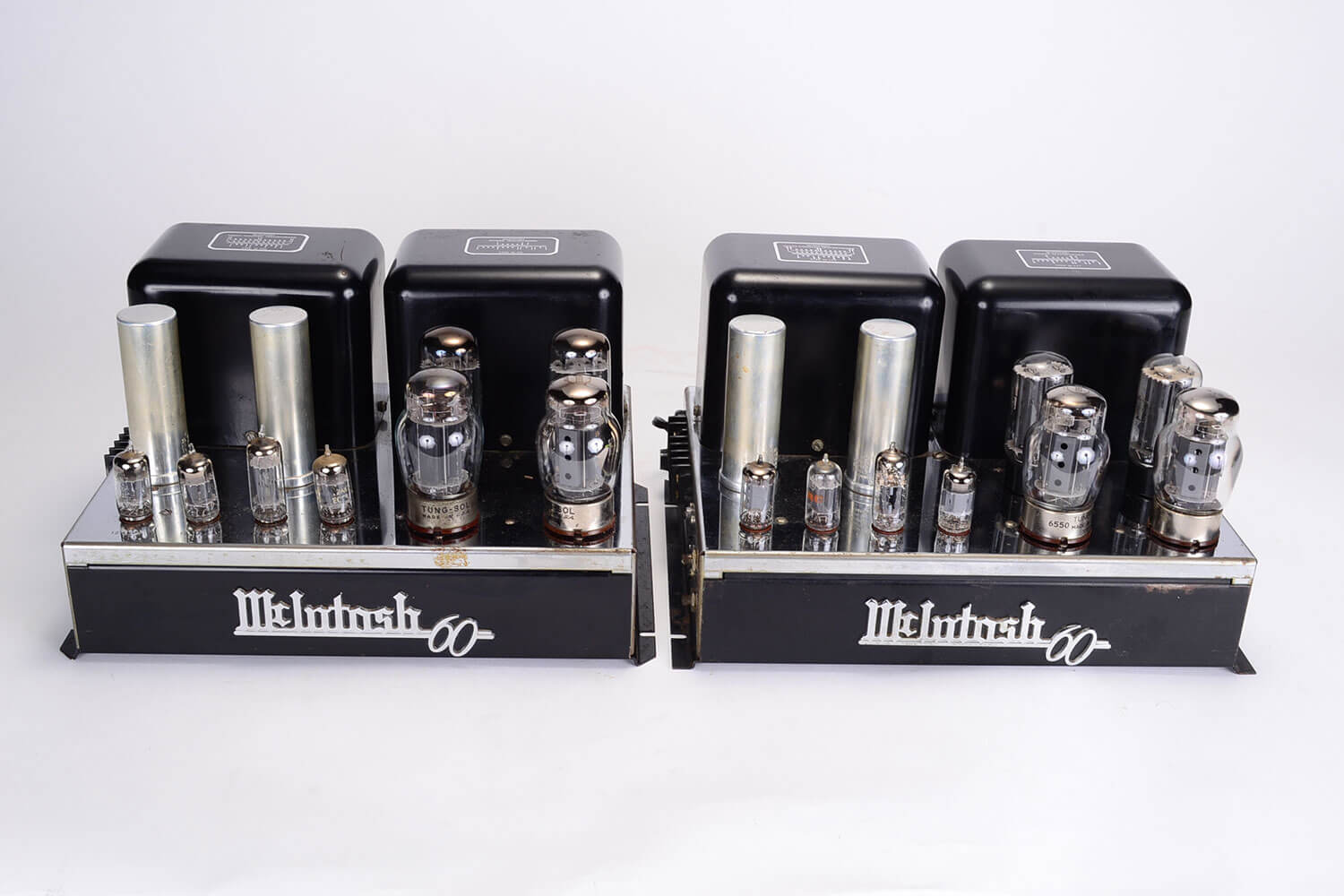
McIntosh MC 60
Amplifier -
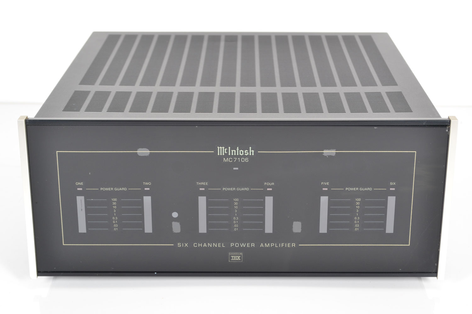
McIntosh MC 7106
Amplifier -
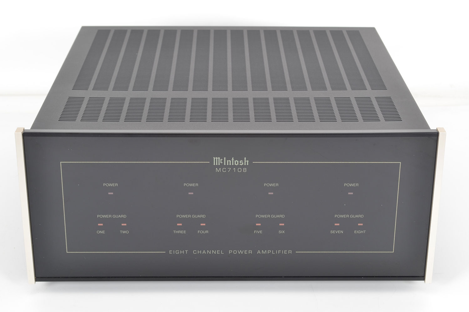
McIntosh MC 7108
Amplifier -
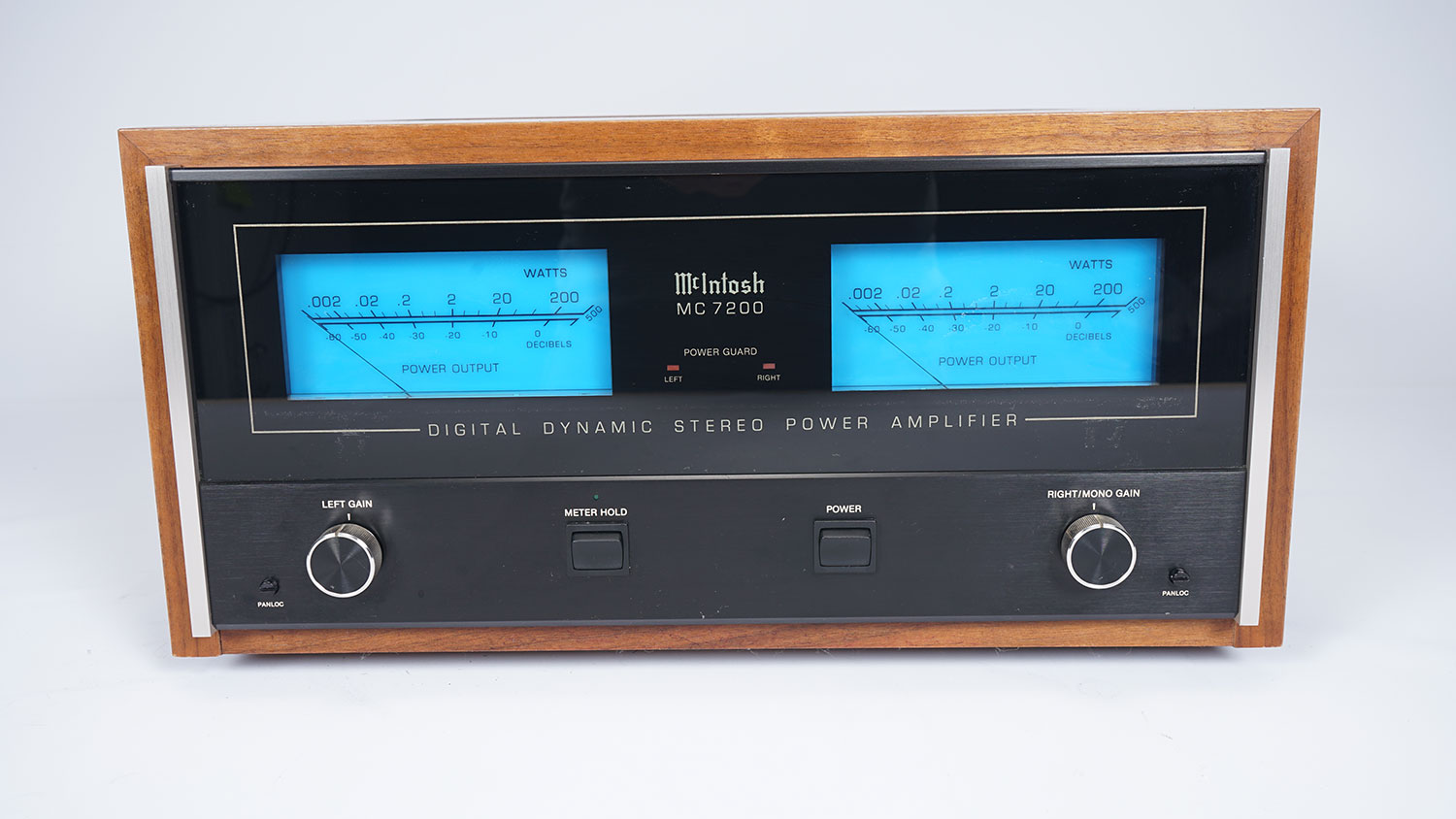
McIntosh MC 7200
Amplifier -
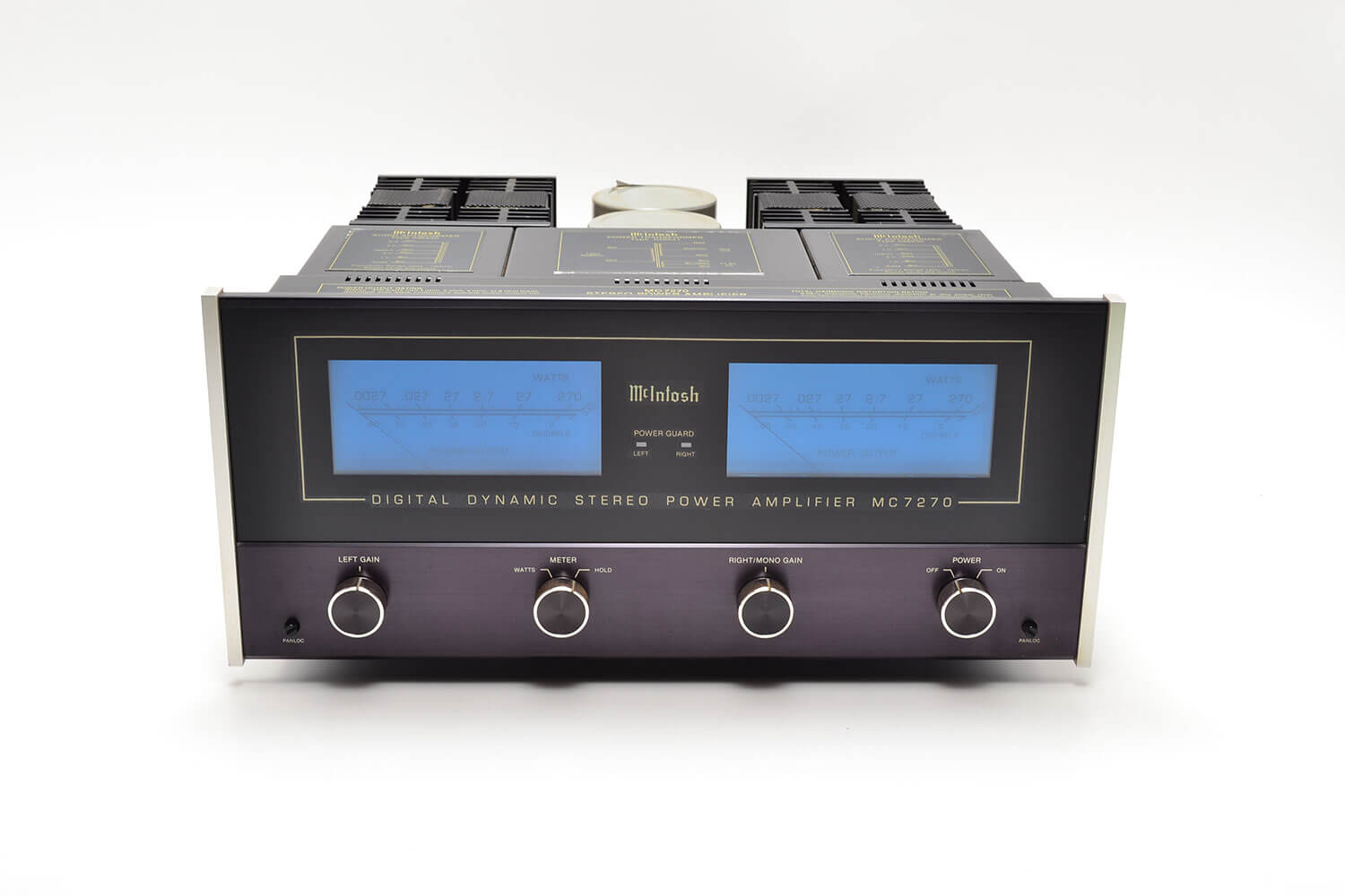
McIntosh MC 7270
Amplifier -
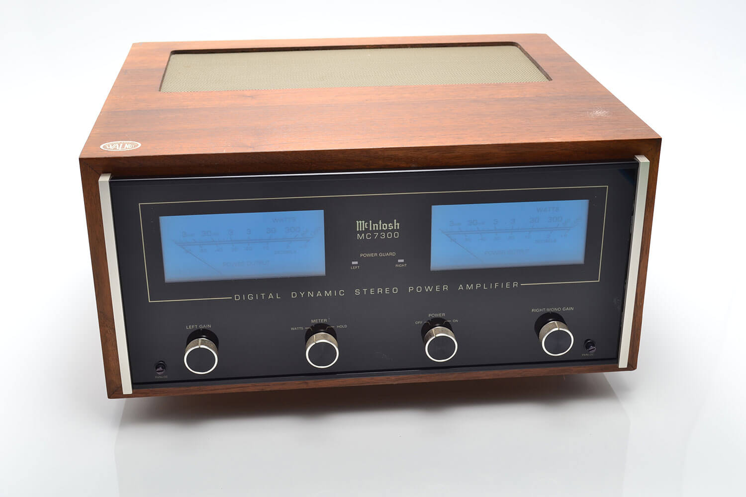
McIntosh MC 7300
Amplifier -
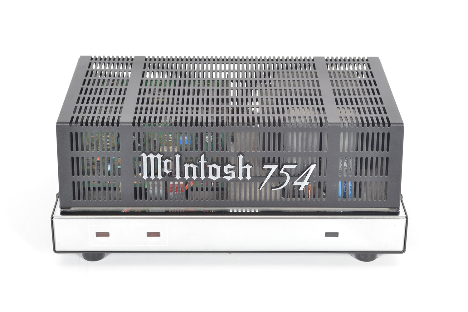
McIntosh MC 754
Amplifier -
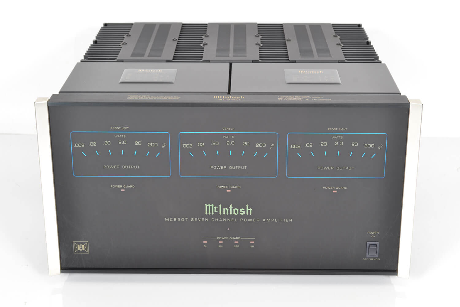
McIntosh MC 8207
Amplifier -
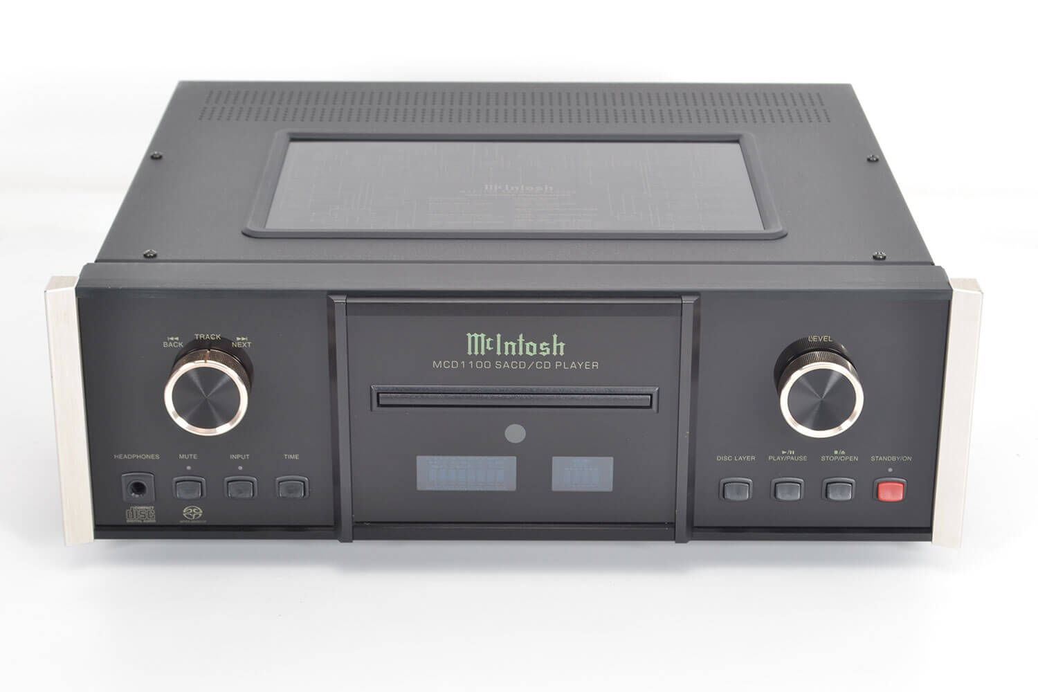
McIntosh MD 1100
Cd player -
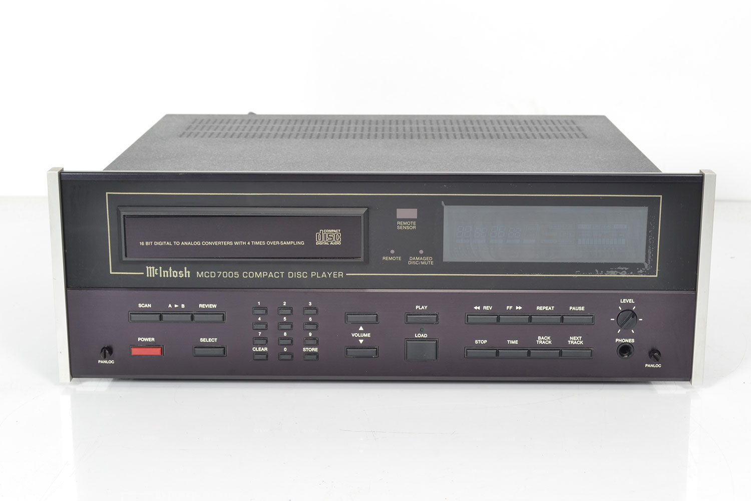
McIntosh MD 7005
Cd player -
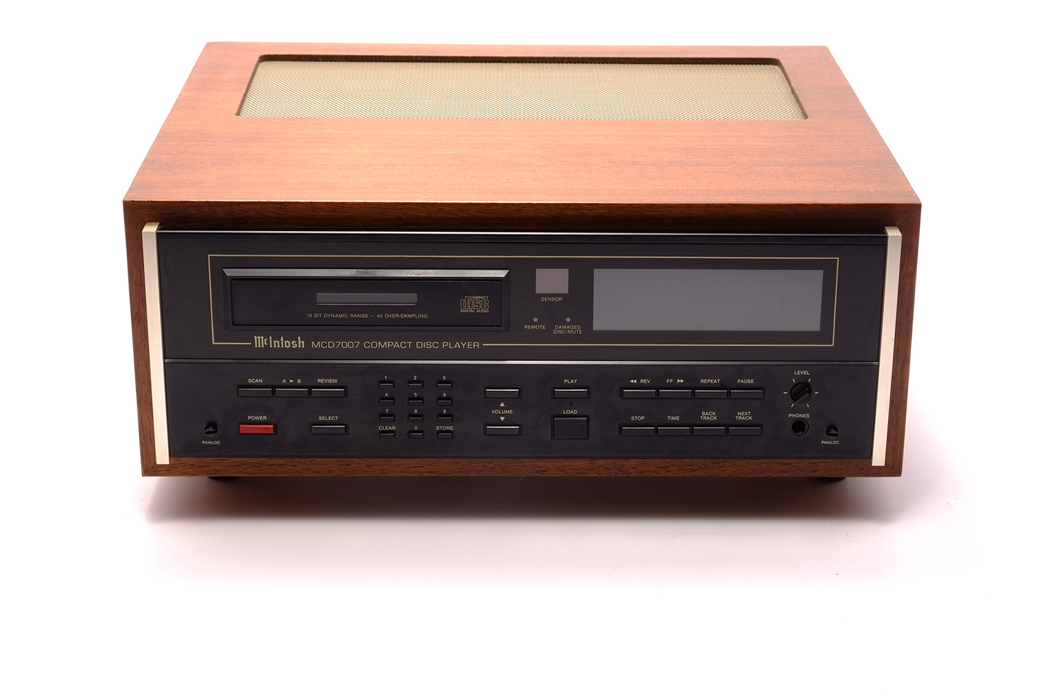
McIntosh MCD 7007
Cd player -
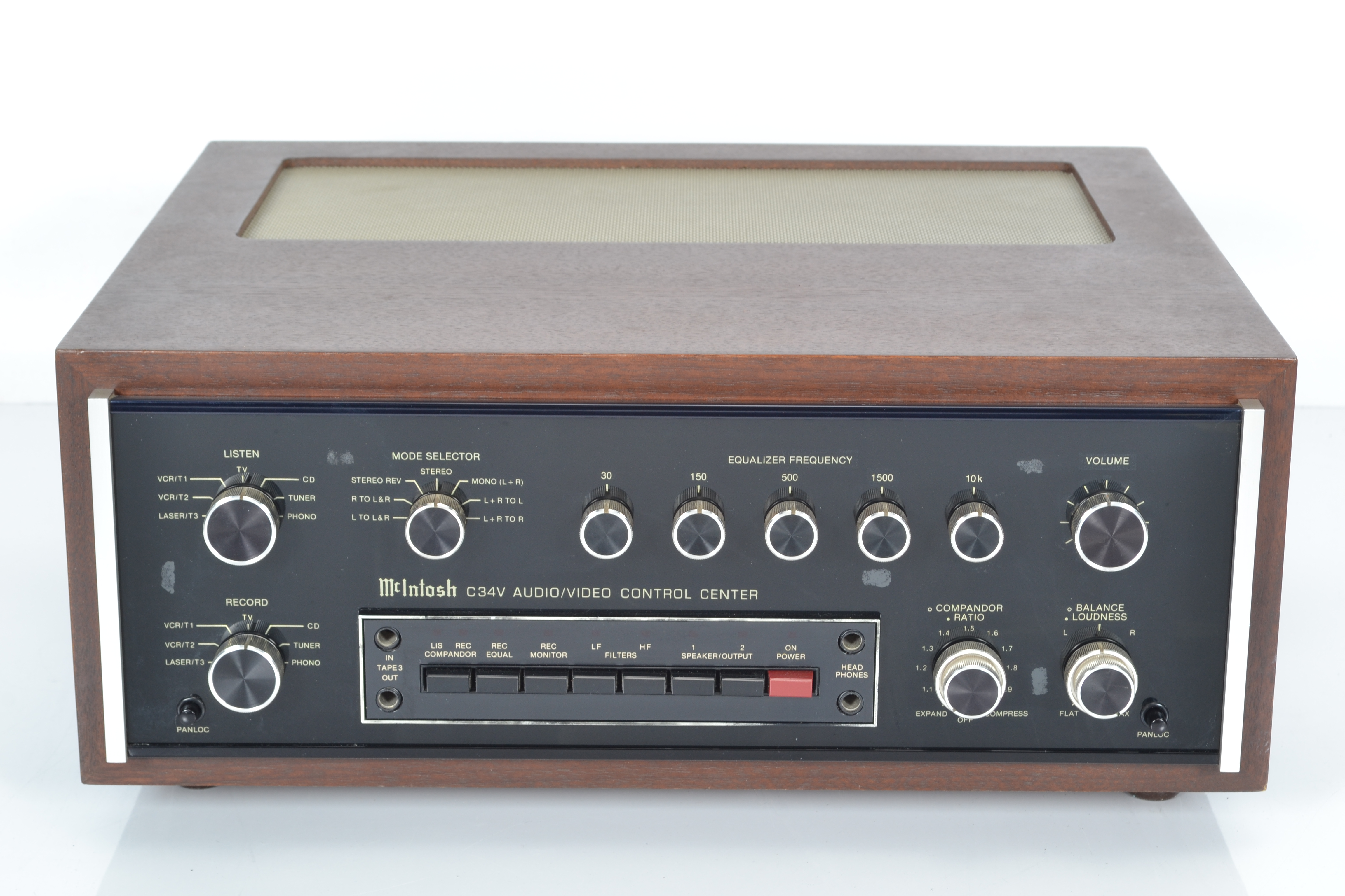
McIntosh C34V
Audio / video control center -
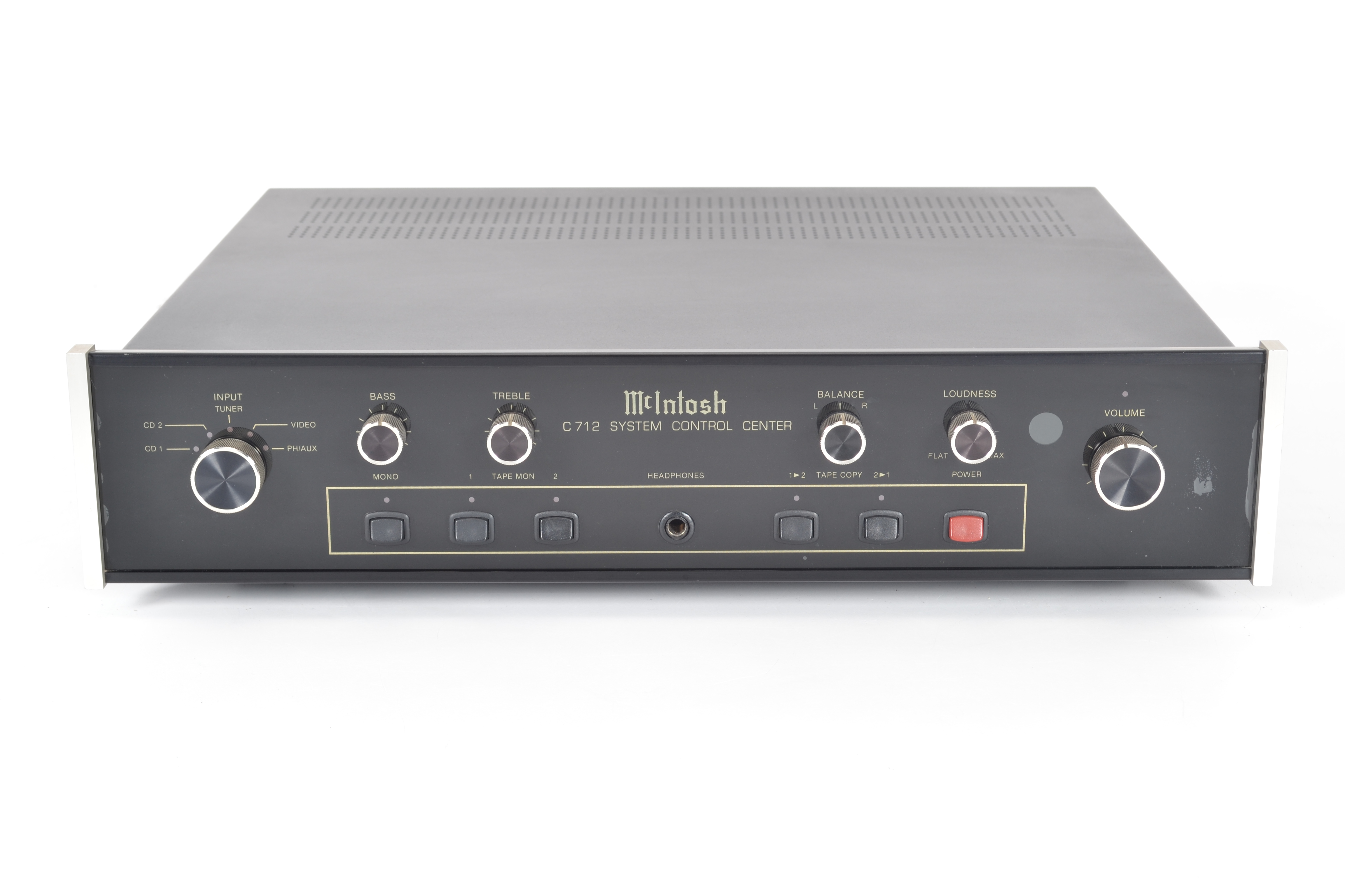
McIntosh C712
System control center preamplifier -
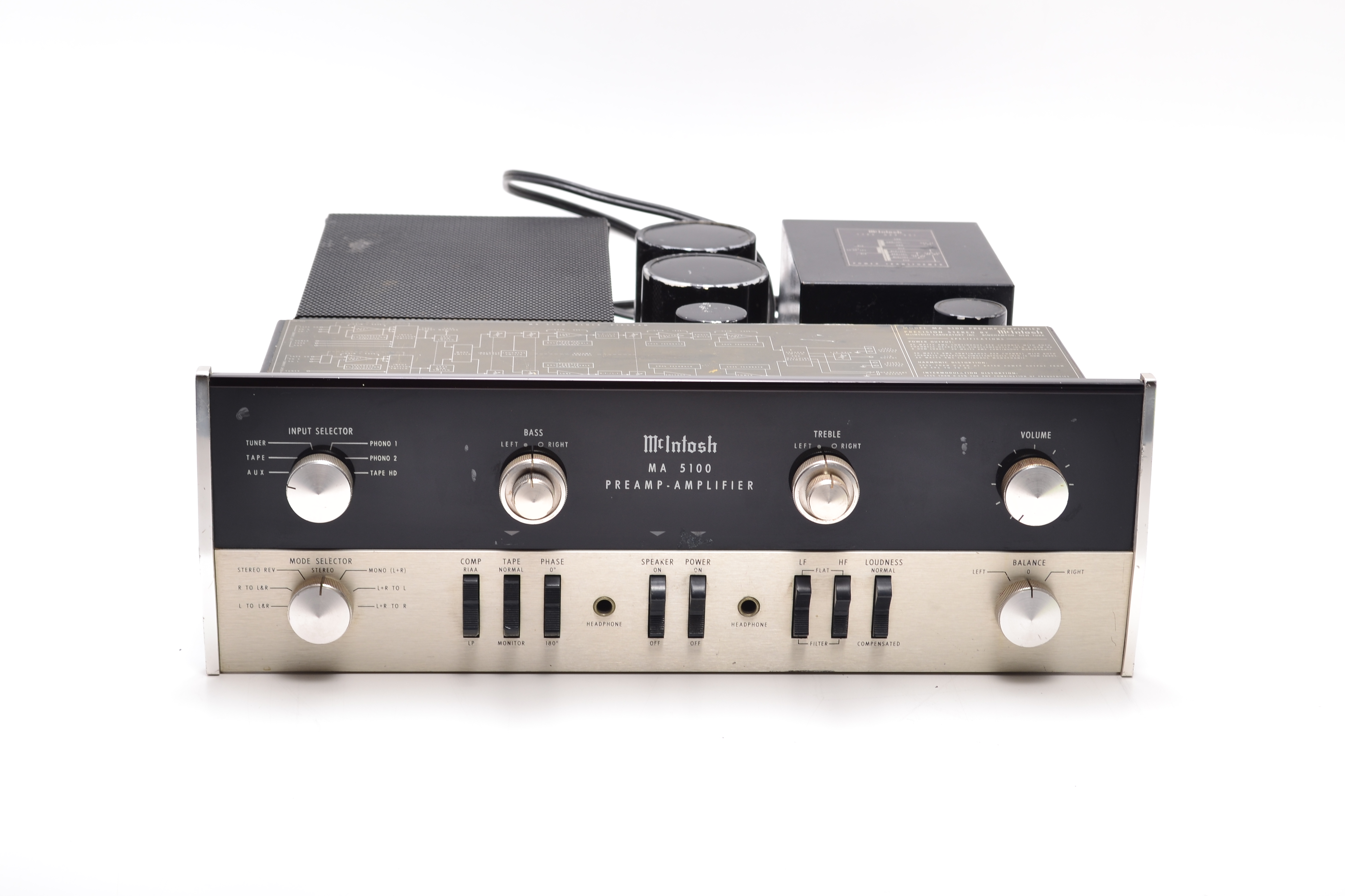
McIntosh MA 5100
Integrated amplifier -
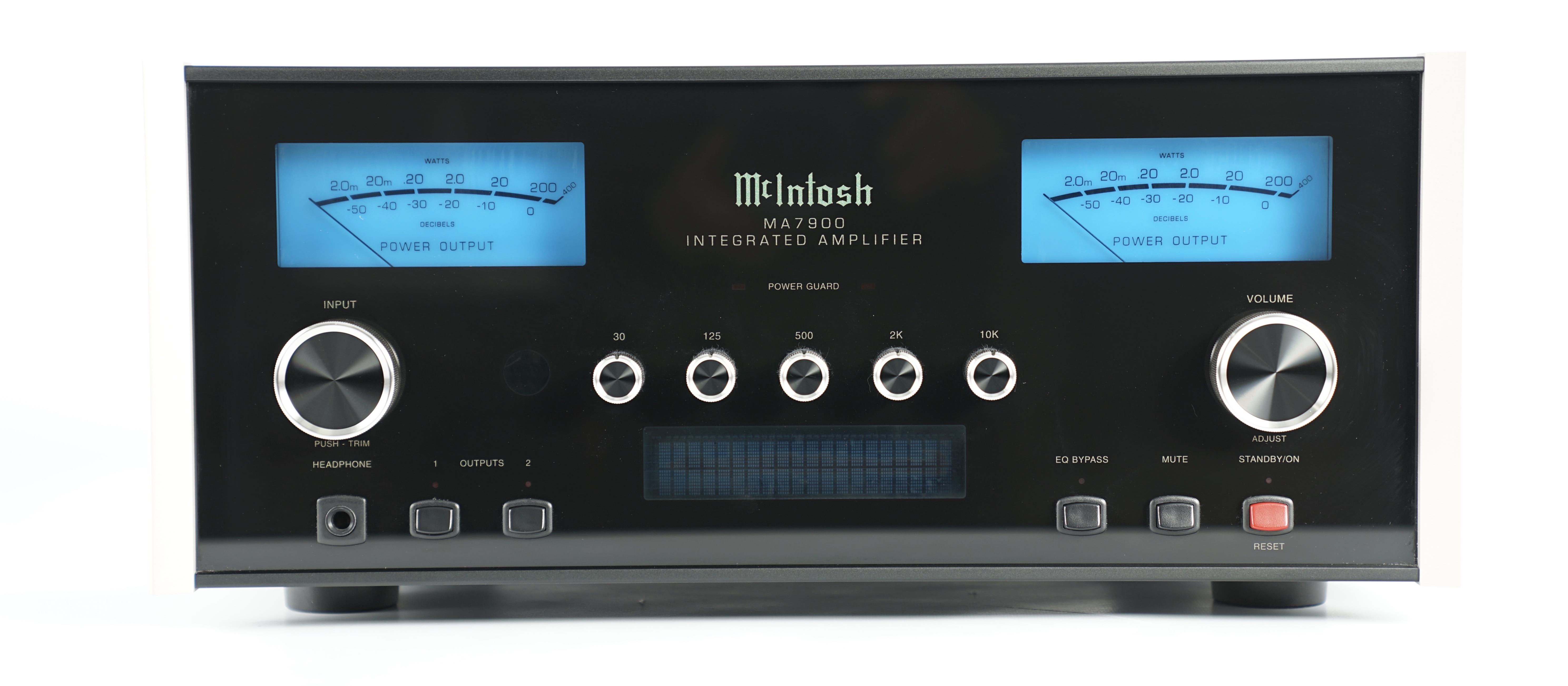
McIntosh MA 7900
Integrated amplifier -
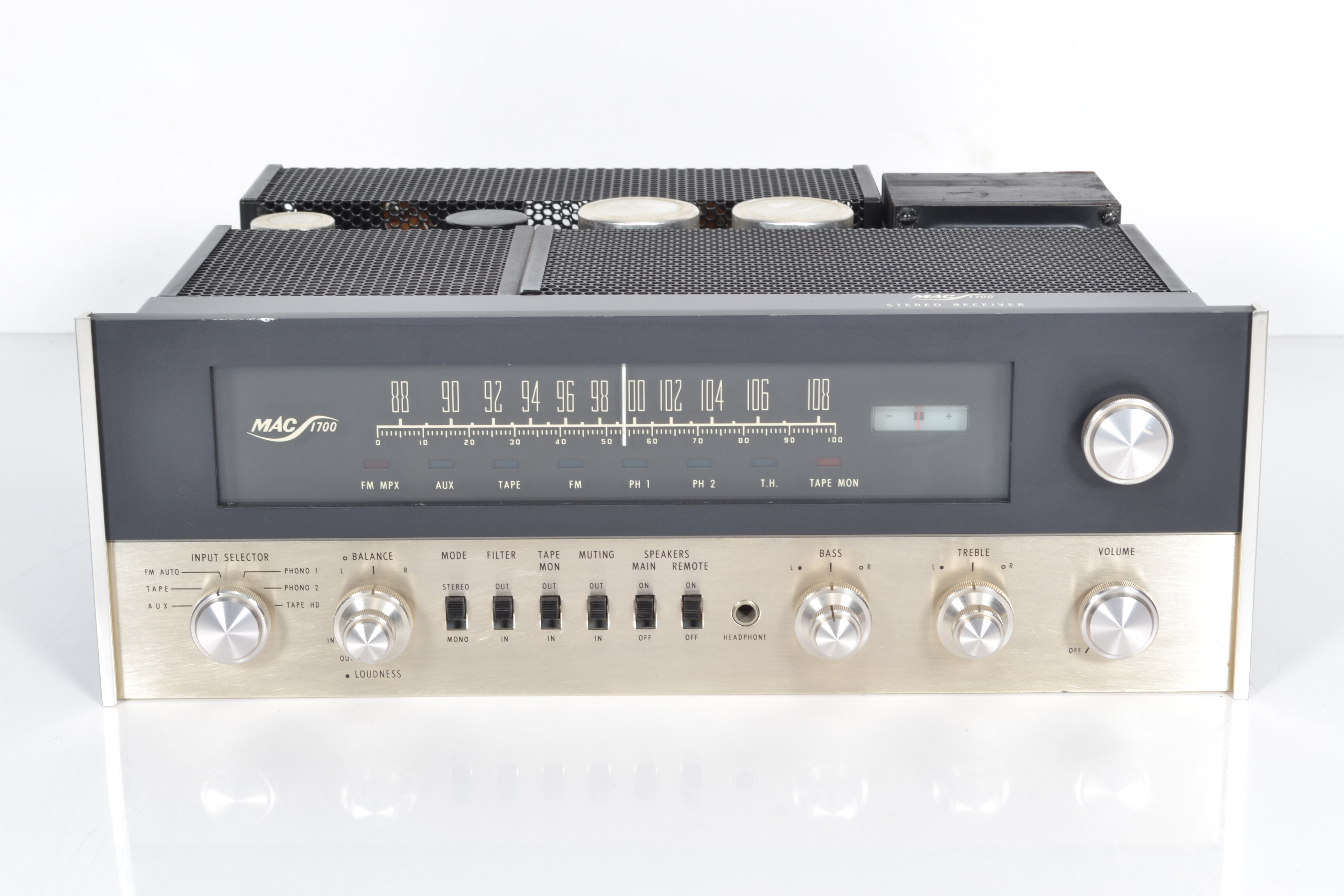
McIntosh MAC 1700
Stereo receiver -
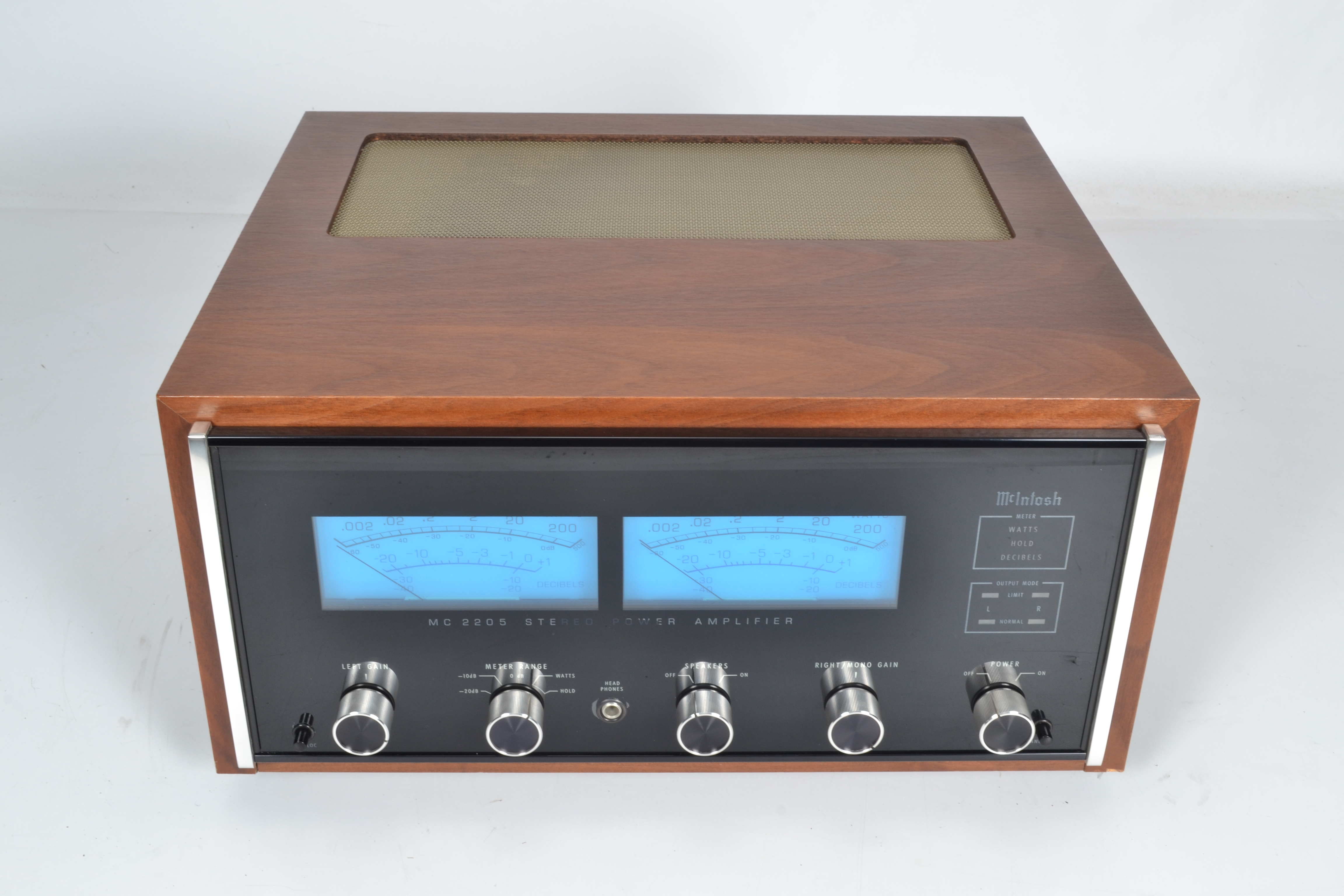
McIntosh MC 2205
Power amplifier -
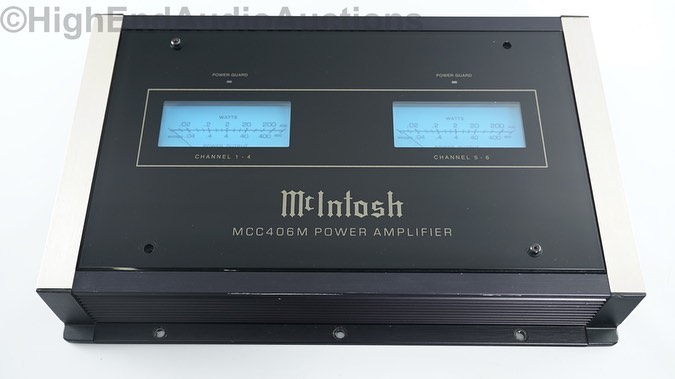
McIntosh MCC406M
Car audio -
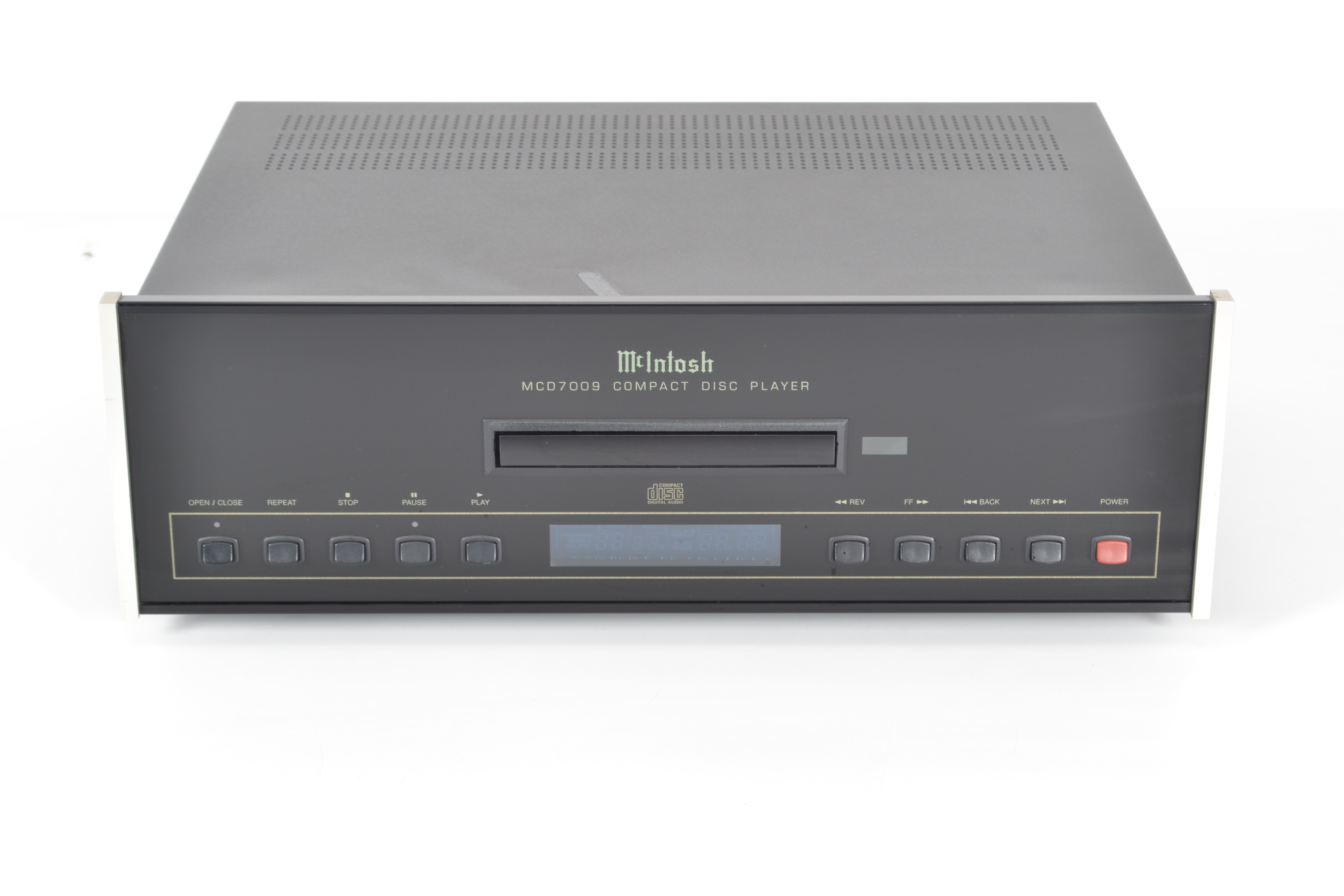
McIntosh MCD 7009
Cd player -
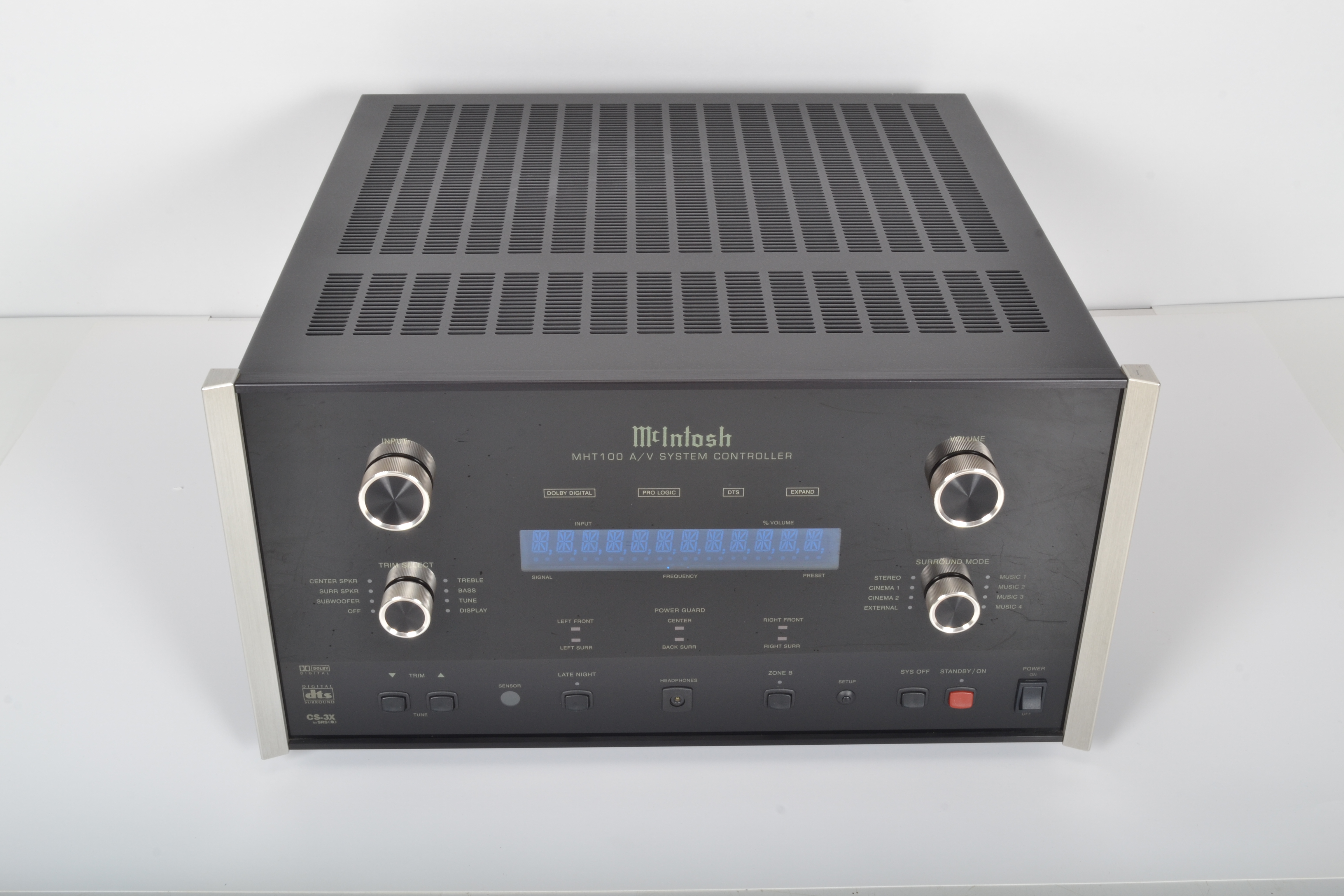
McIntosh MHT 100
A/v system controller -
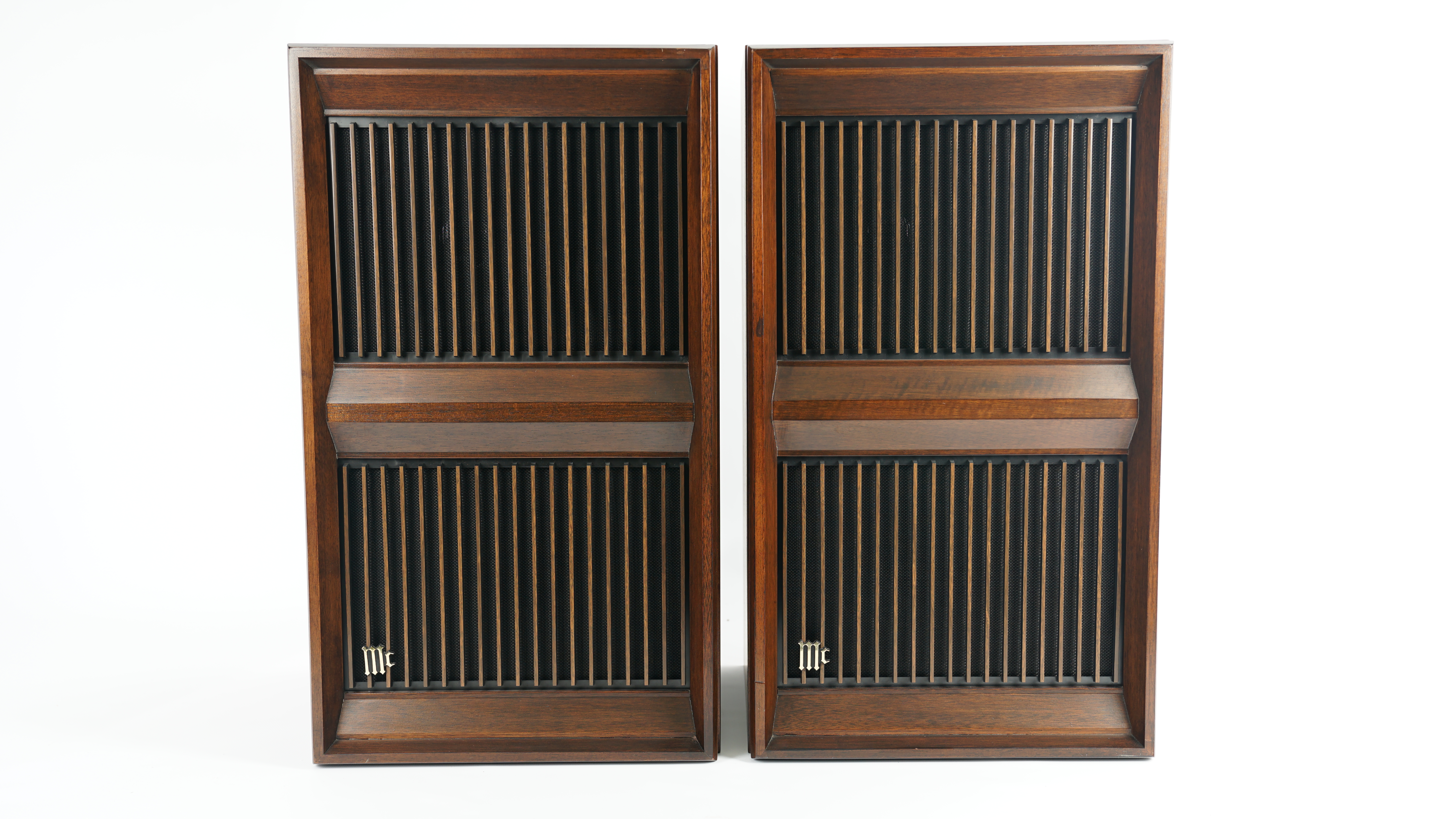
McIntosh ML 10C
Speakers -
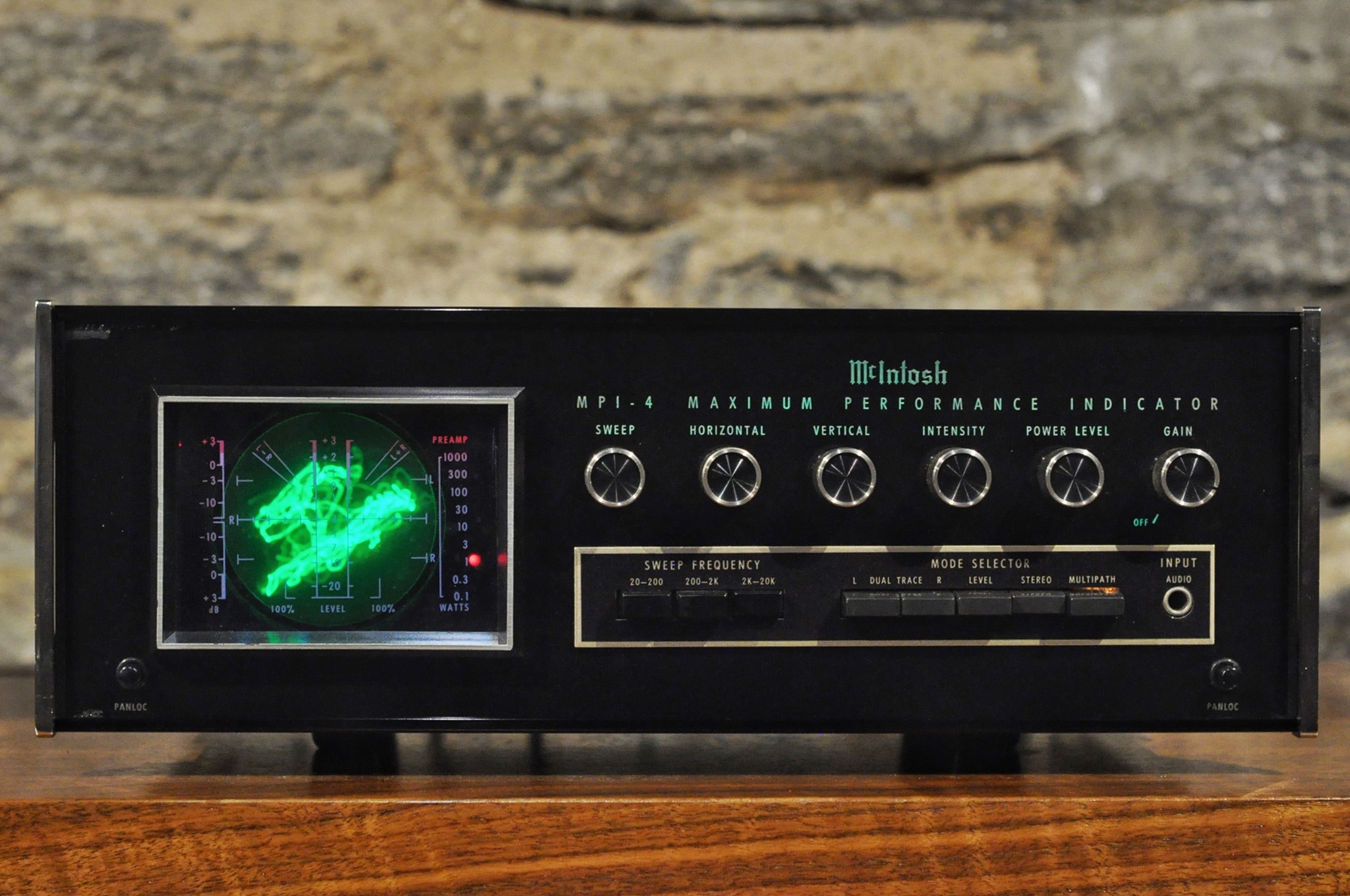
McIntosh MPI-4
Maximum performance indicator -

McIntosh MX 121
A/v control center -
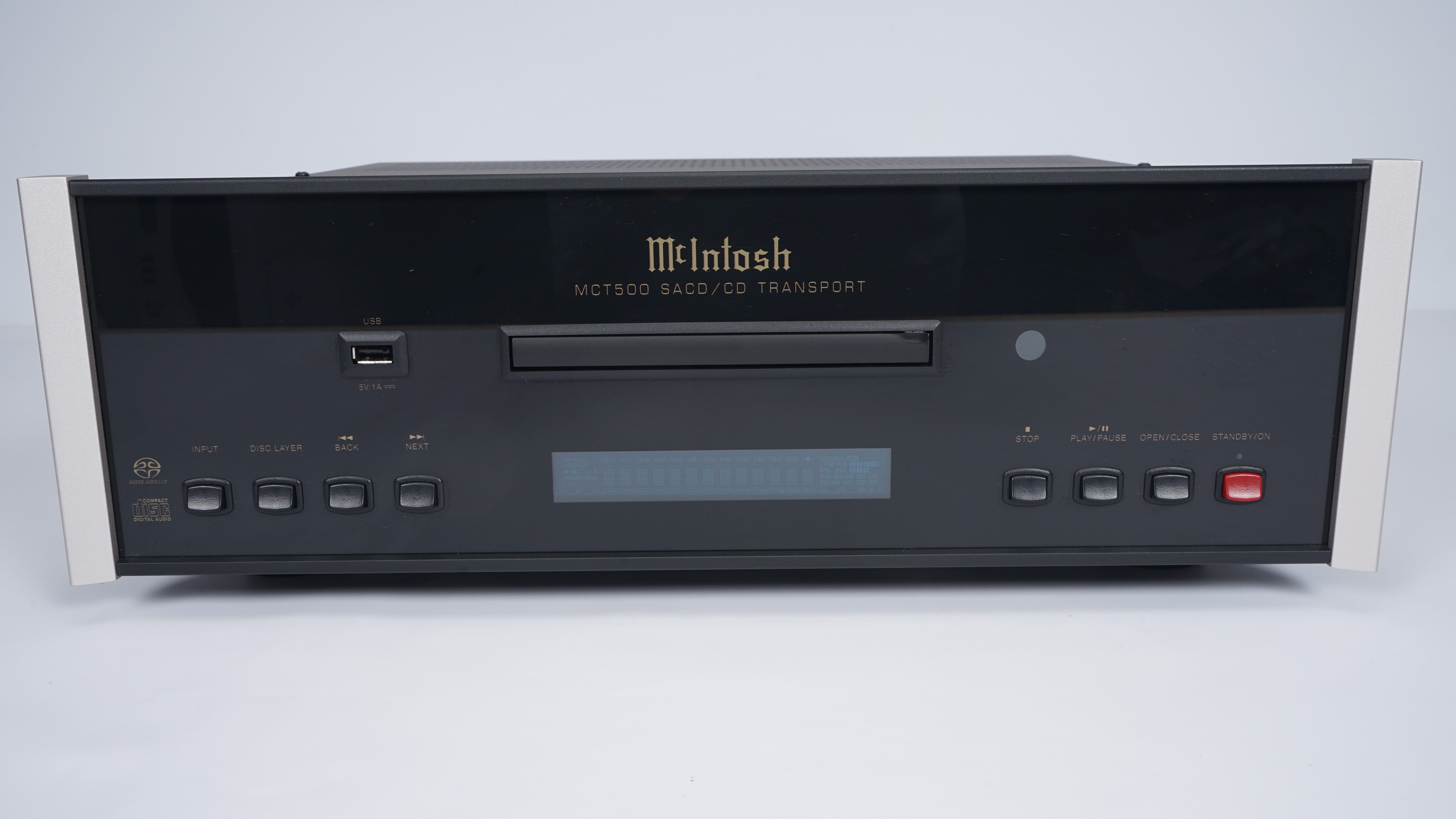
McIntosh MCT 500
Cd-transport -
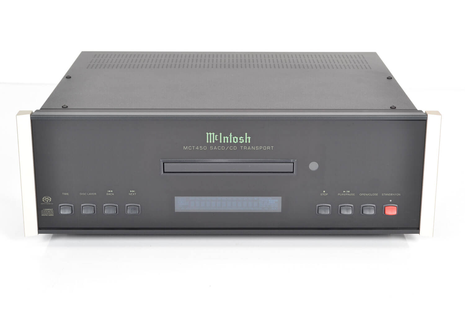
McIntosh MCT 450
Cd player -
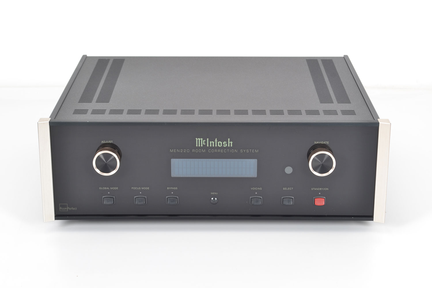
McIntosh MEN 220
Room collection -
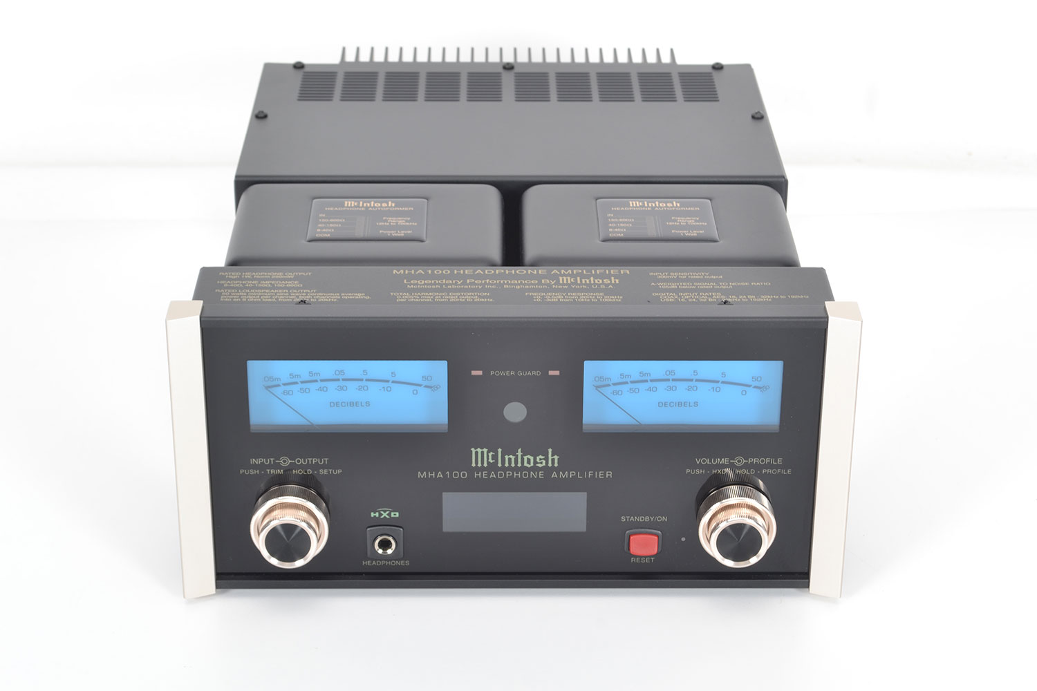
McIntosh MHA 100
Headphone amplifier -
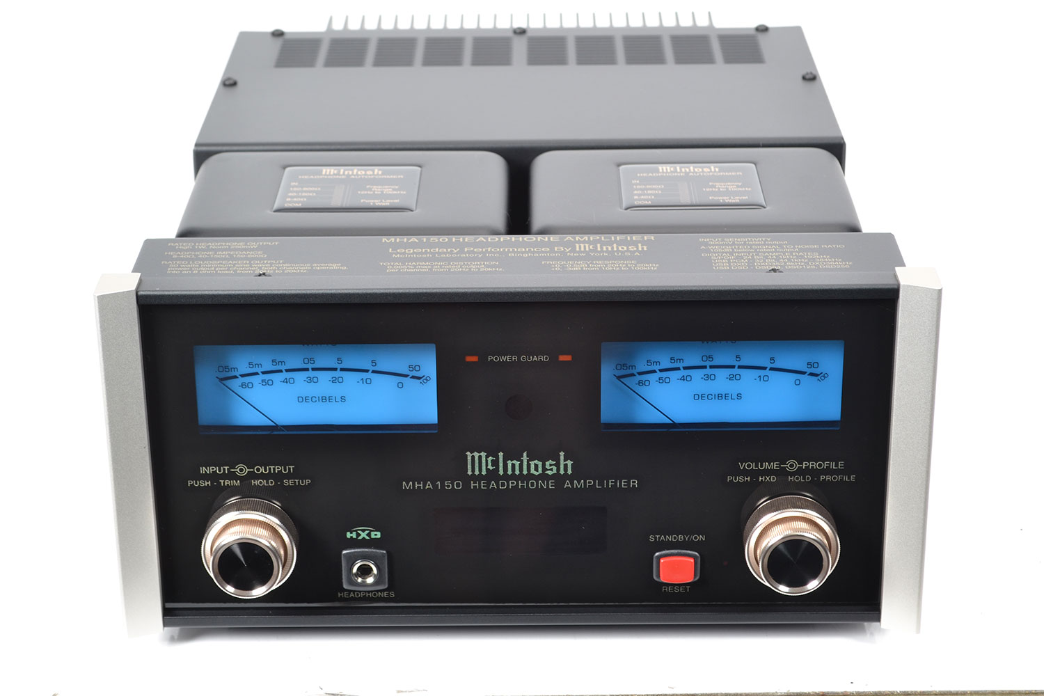
McIntosh MHA 150
Headphone amplifier -
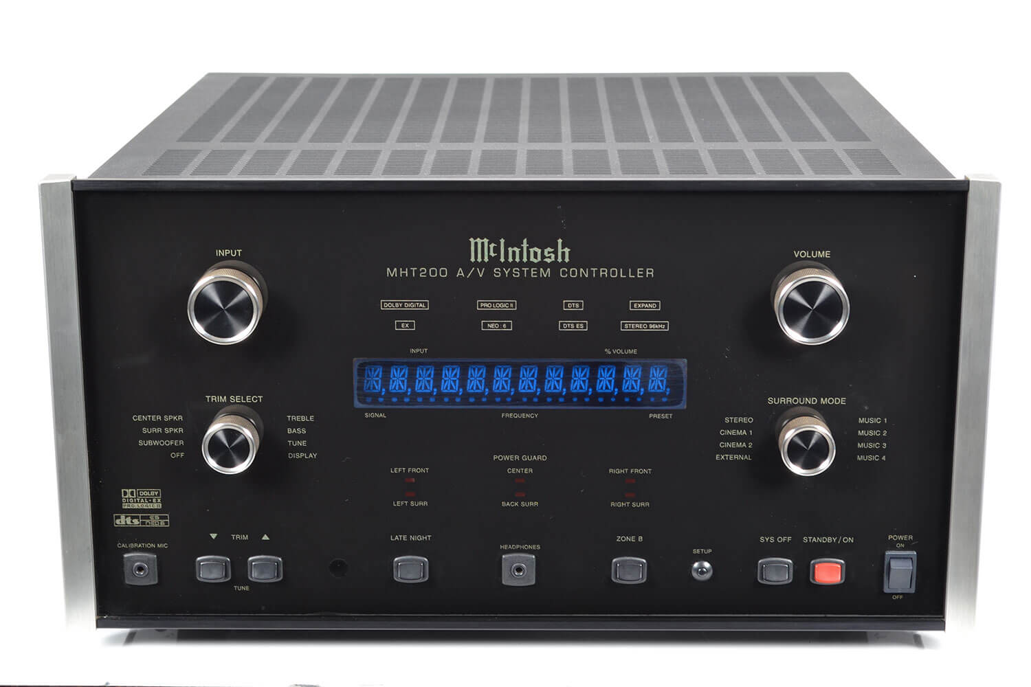
McIntosh MHT 200
Surround sound processor -
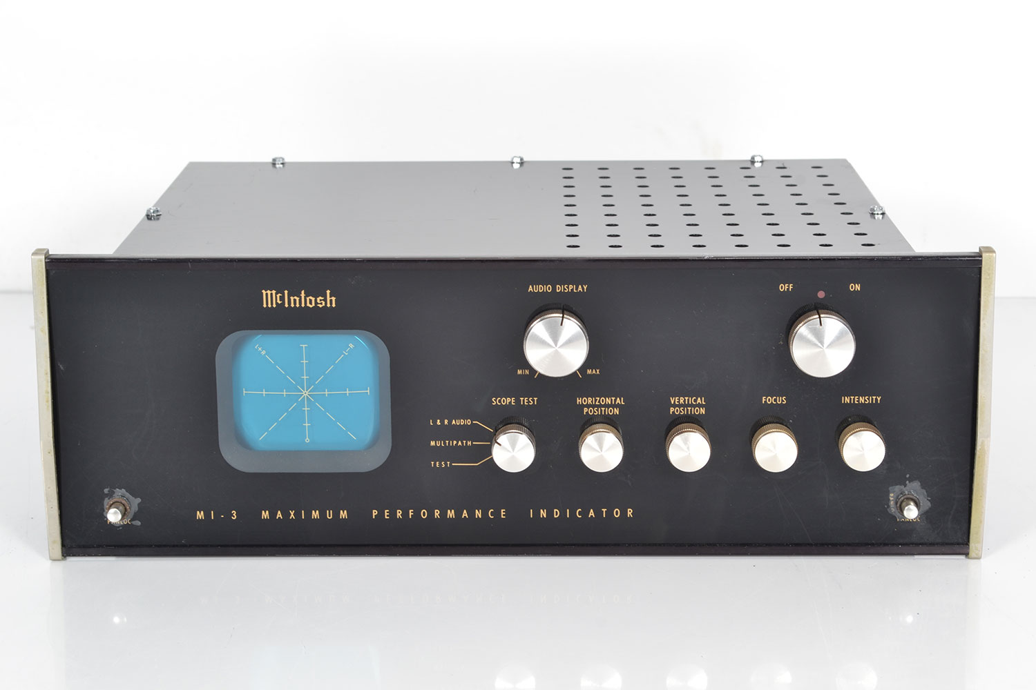
McIntosh MI 3
Performance-scope -
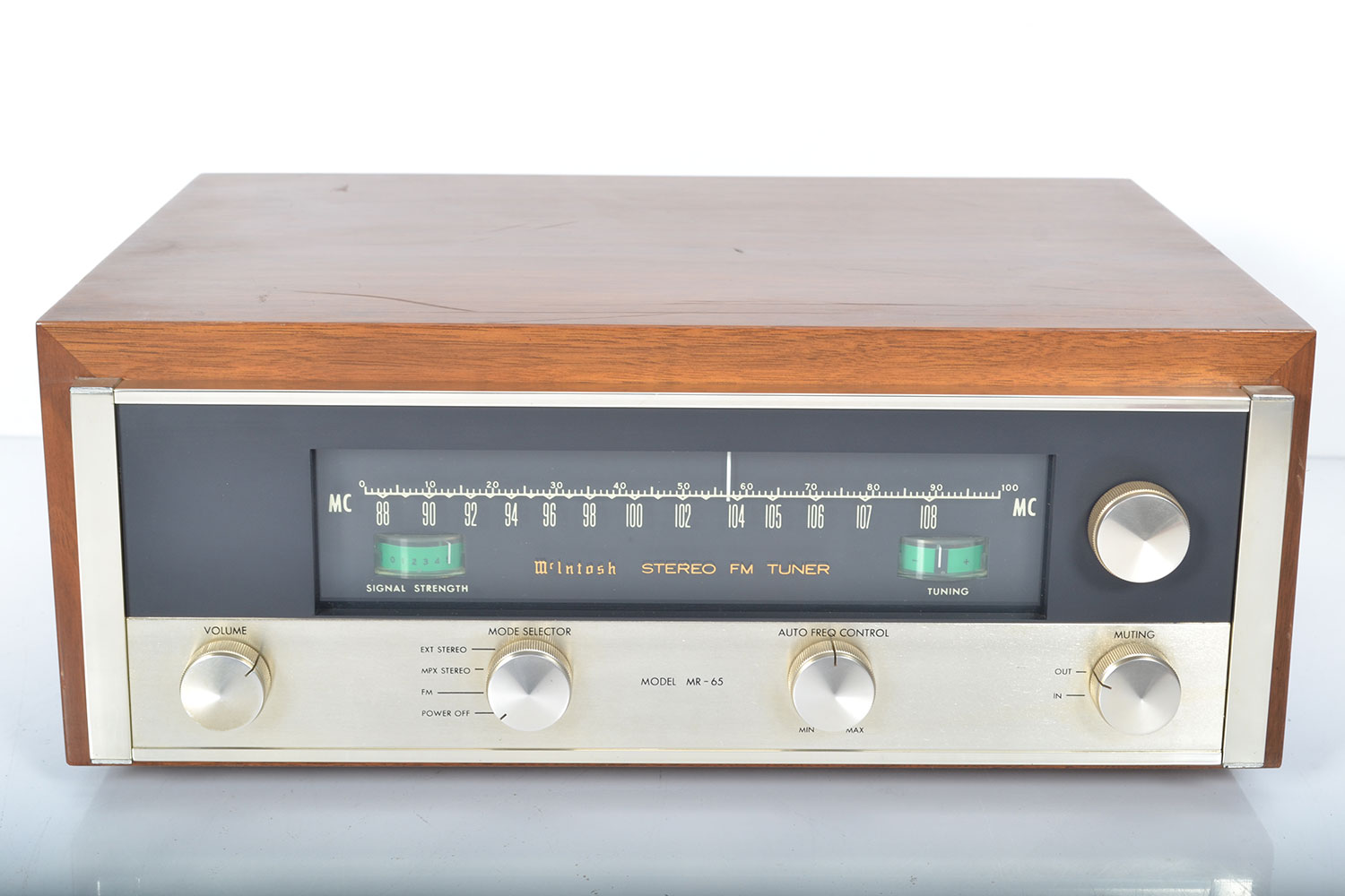
McIntosh MR 65a
Tuner -
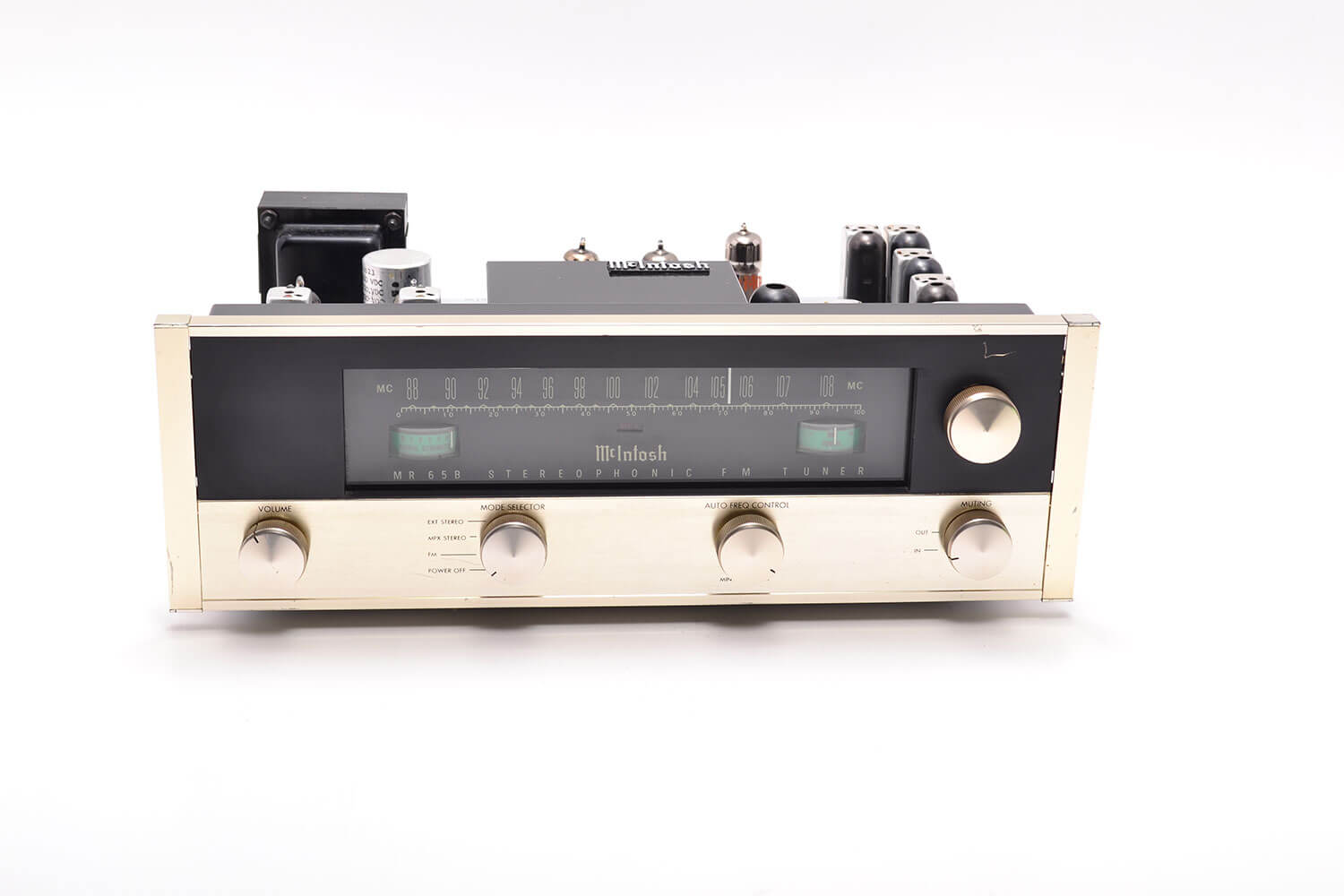
McIntosh MR 65b
Tuner -
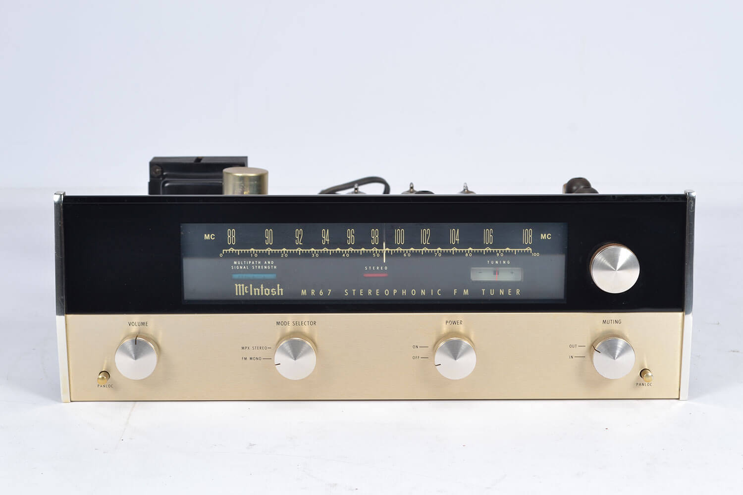
McIntosh MR 67
Tuner -
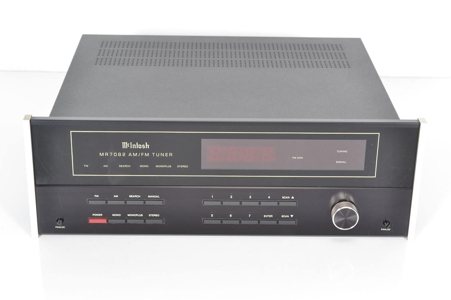
McIntosh MR 7082
Tuner -
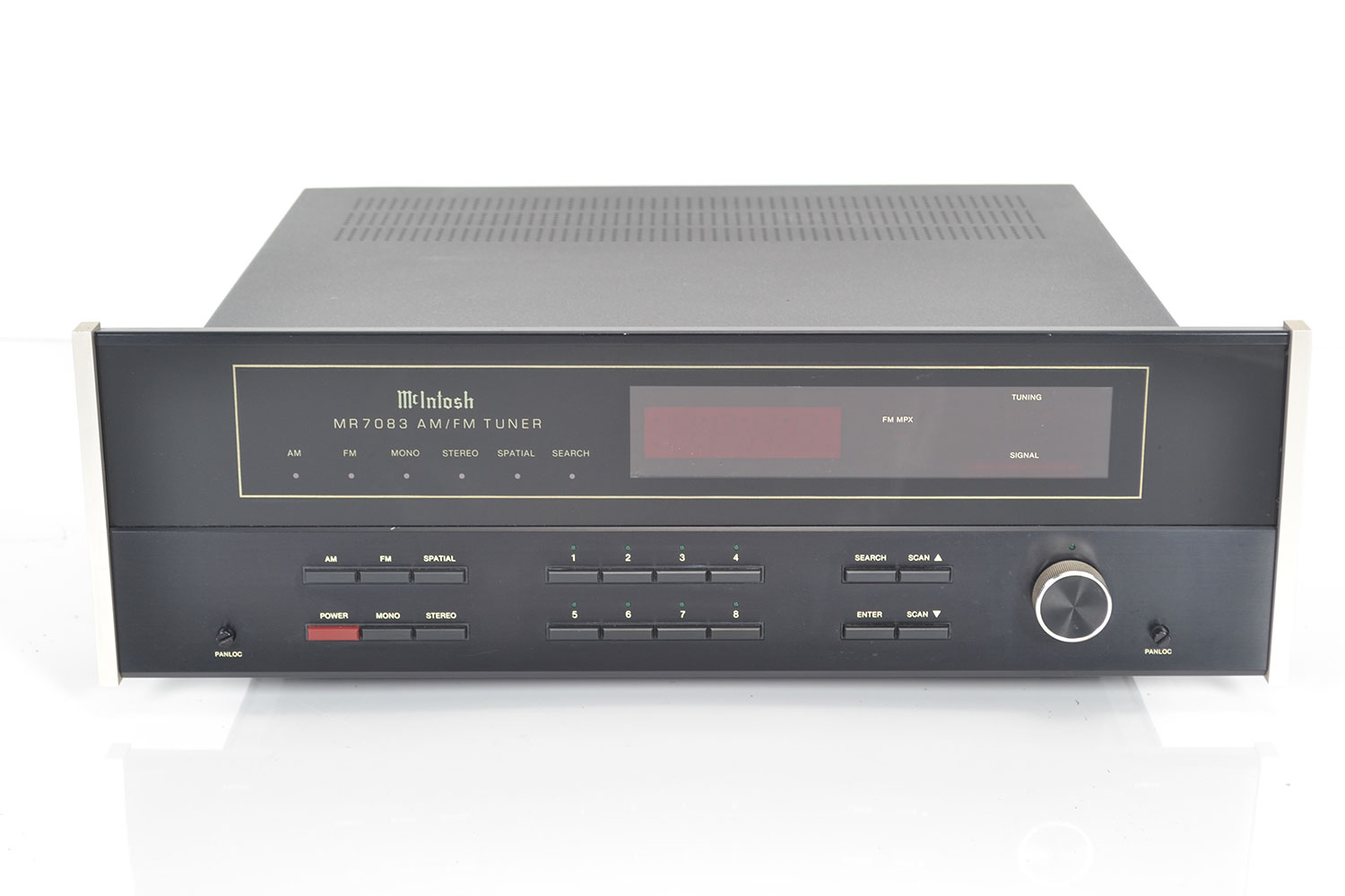
McIntosh MR 7083
Tuner -
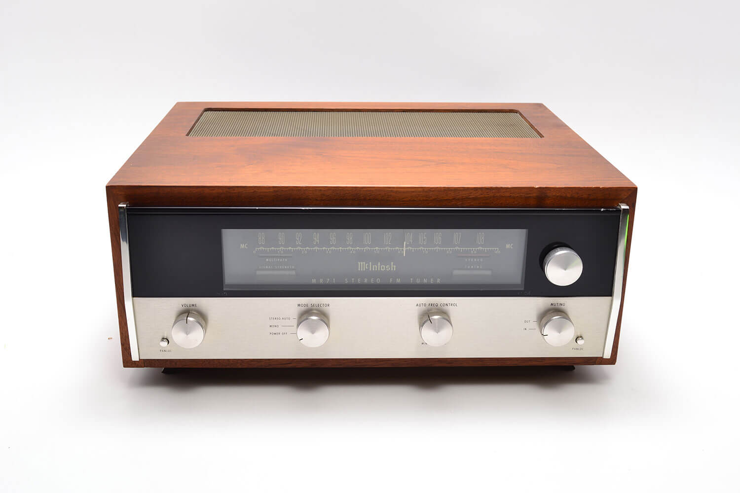
McIntosh MR 71
Tuner -
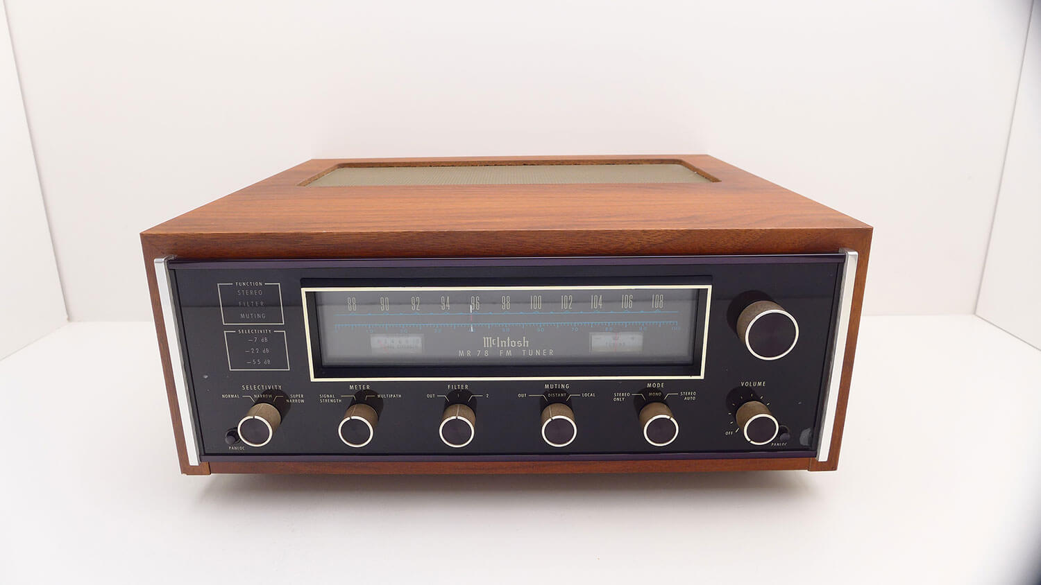
McIntosh MR 78
Tuner -
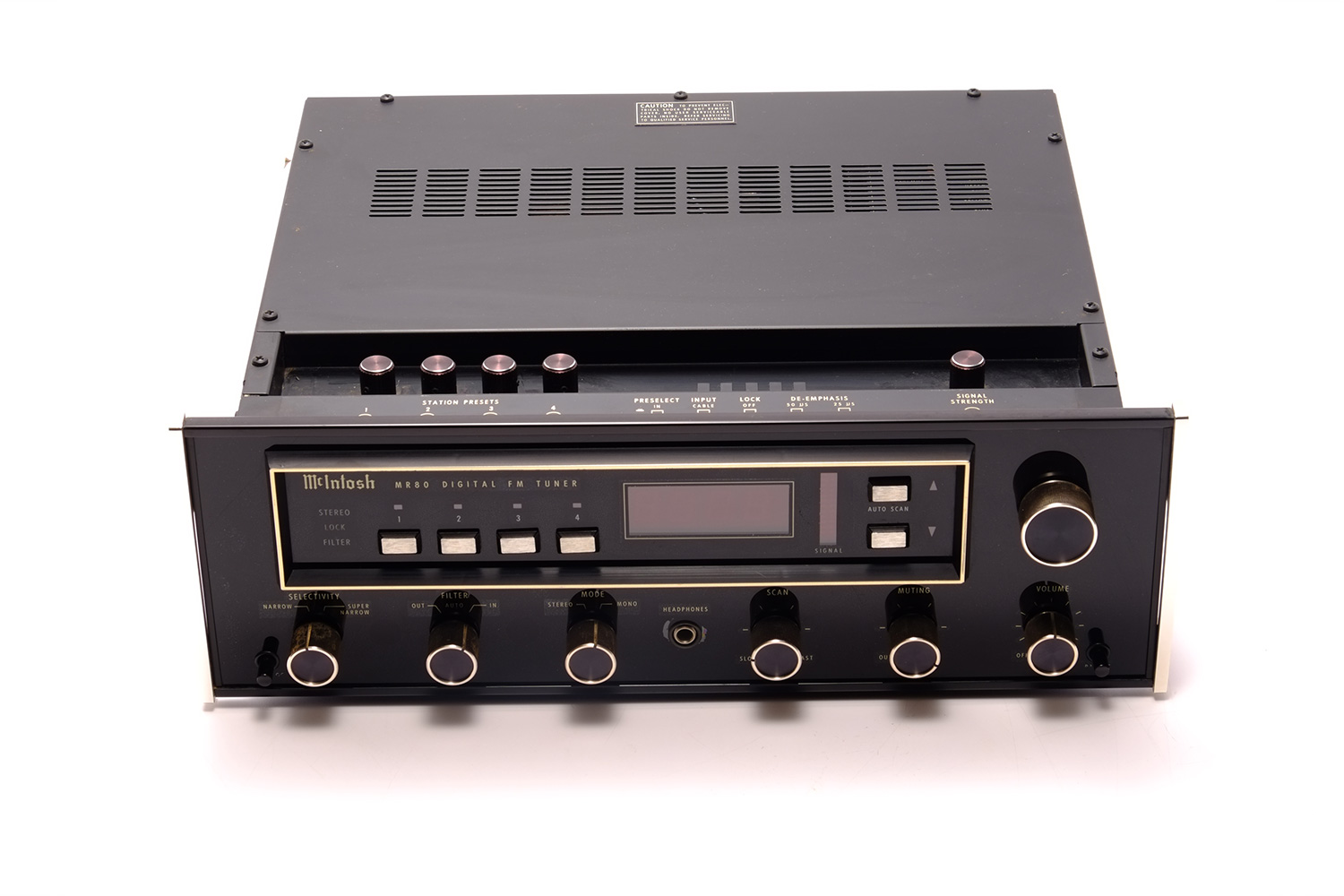
McIntosh MR 80
Tuner -
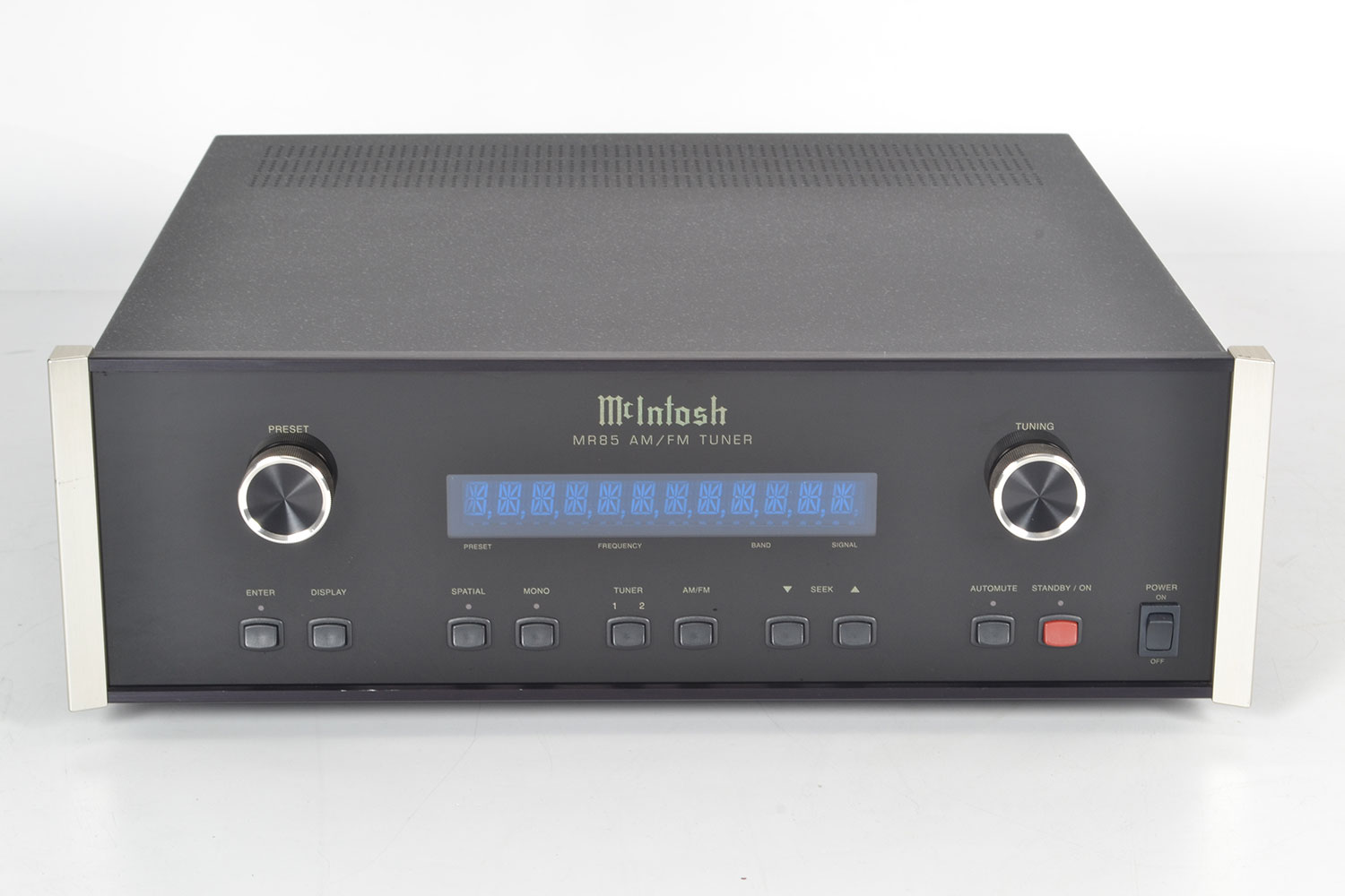
McIntosh MR 85
Tuner -
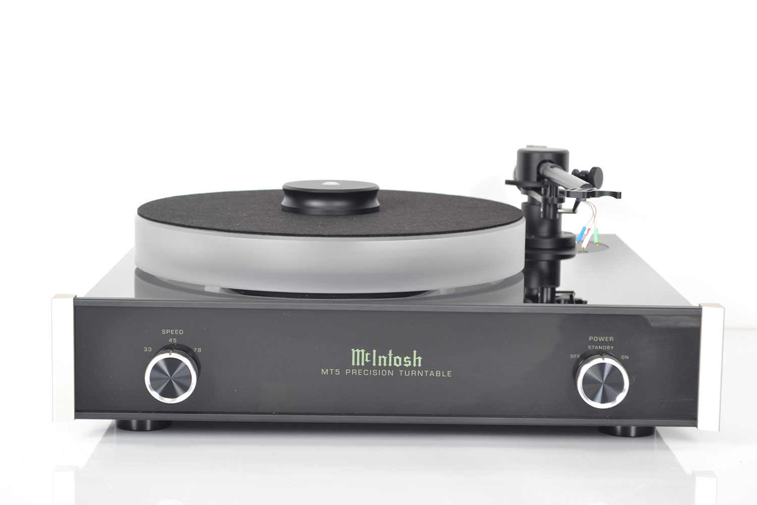
McIntosh MT5
Turntable -
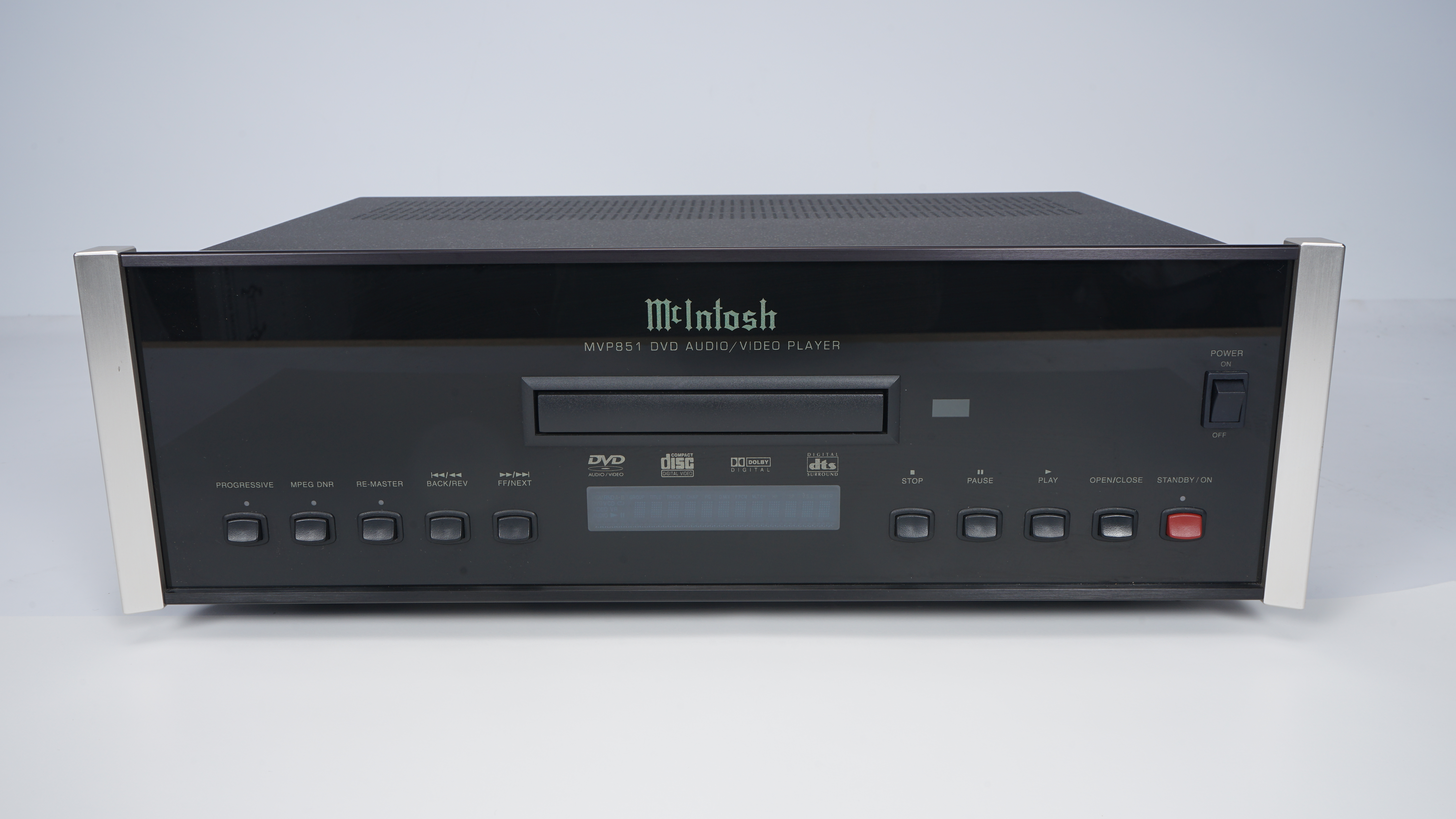
McIntosh MVP 851
Amplifier -
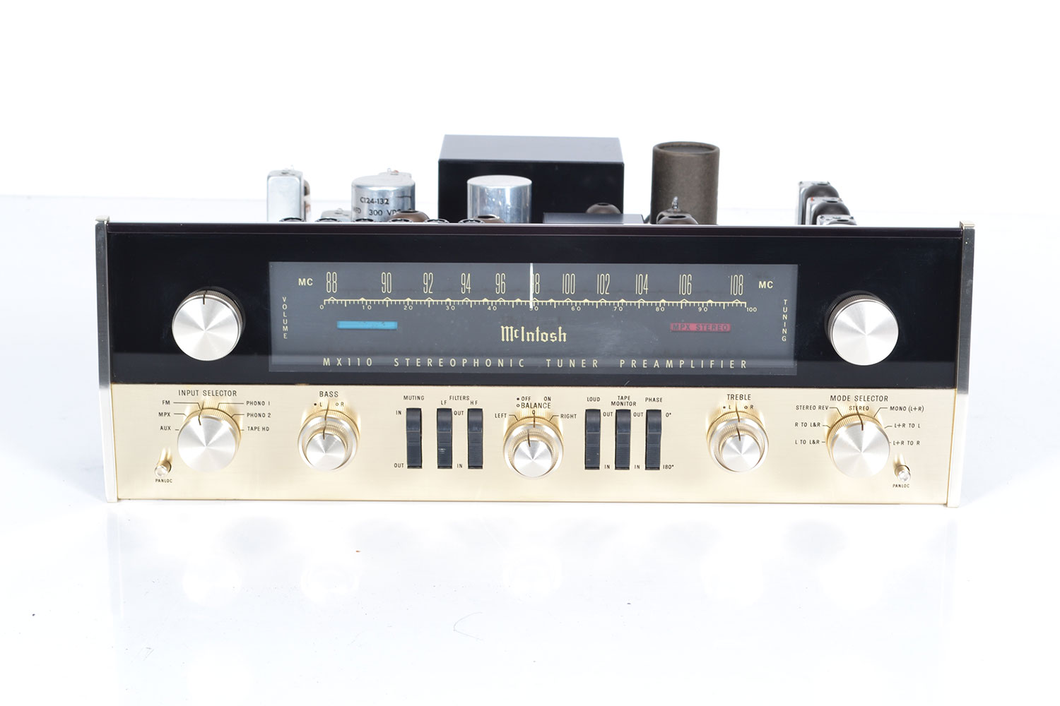
McIntosh MX 110Z
Tuner-preamplifier -
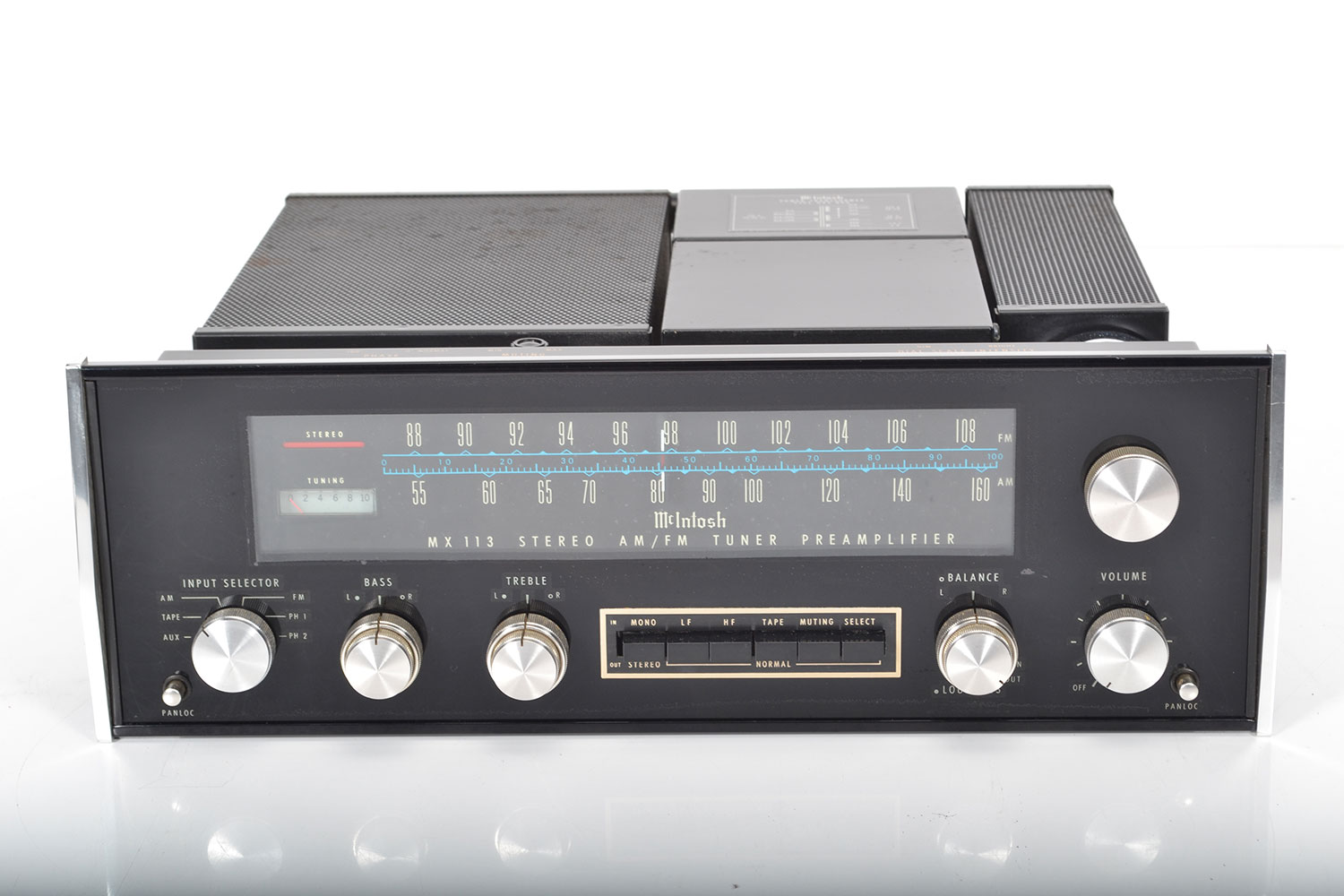
McIntosh MX 113
Tuner-preamplifier -
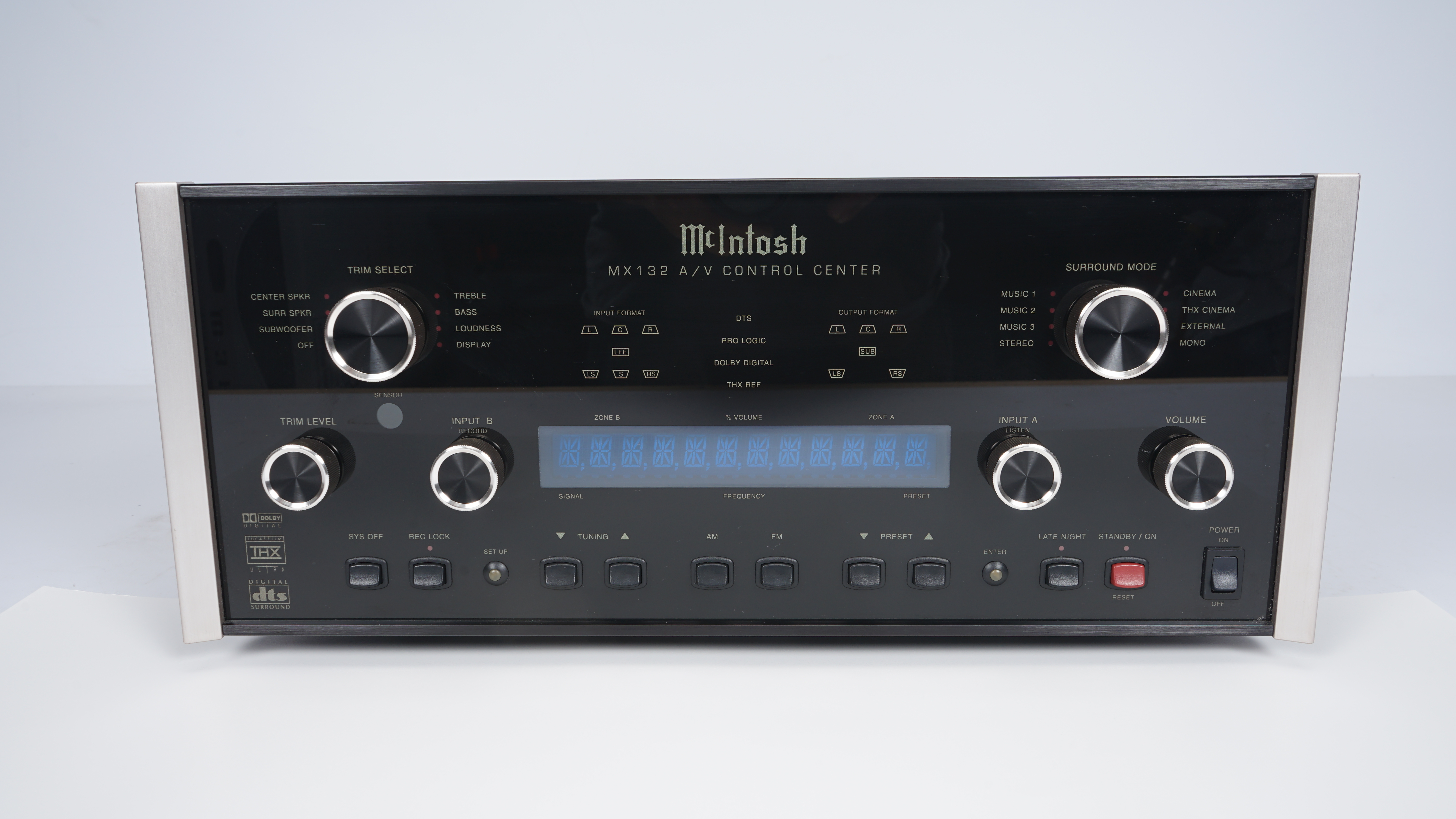
McIntosh MX 132
Av-control-center -
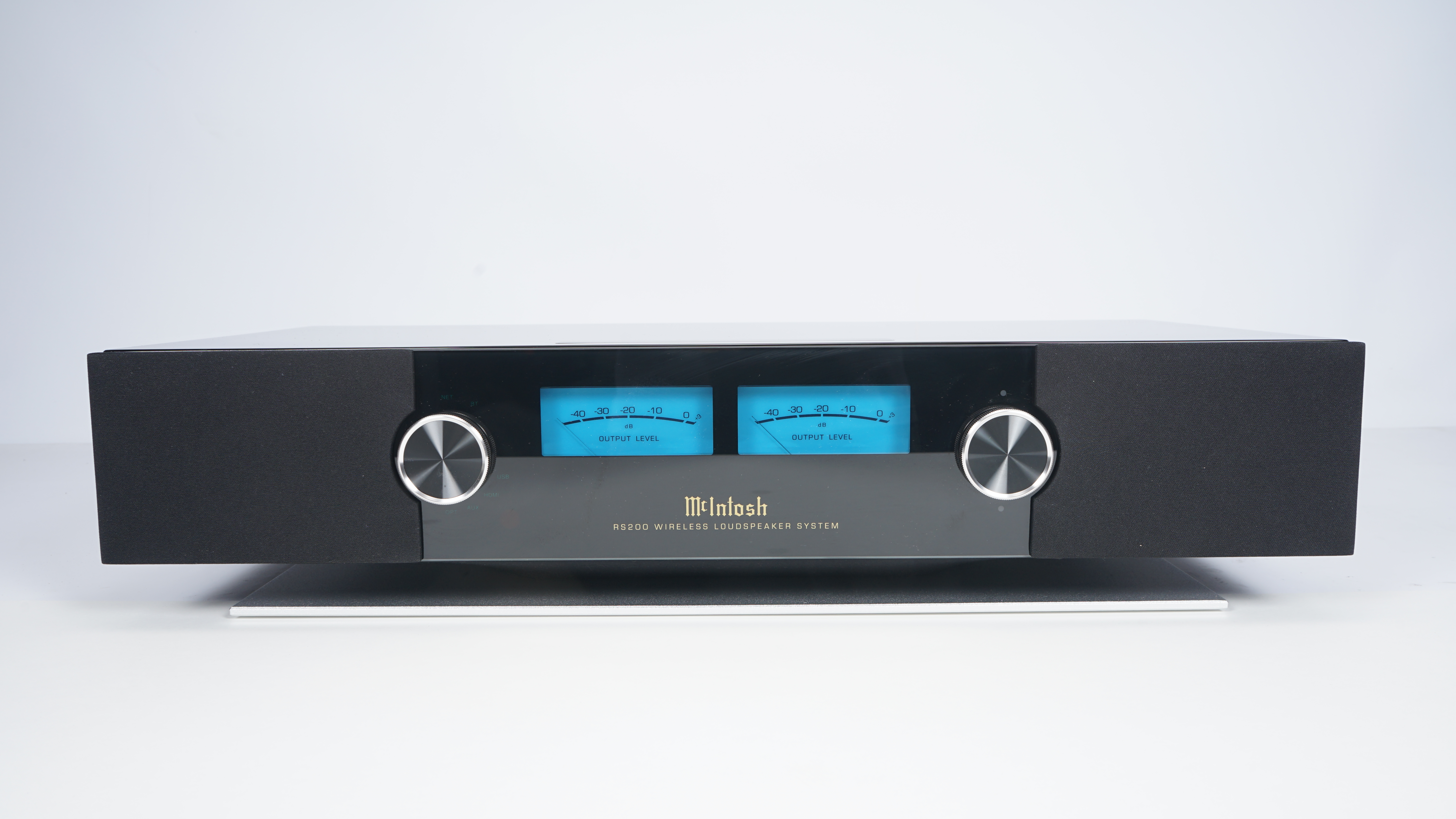
McIntosh RS 200
Wireless-speaker